|
Here are some basic rules of thumb on end mill selection  Navigating the vast array of end mills available in the market can be a daunting task, especially when precision is paramount. To aid in this process, we've outlined a step-by-step guide that addresses crucial considerations for selecting the optimal end mill for your machining needs.
Step 1 – Material Identification: Identify the exact material, its condition (billet, forging, etc.), and hardness (HRC). This information directs you to the Non-Ferrous or Ferrous section of our catalog. Step 2 – Operation Type: Determine whether you'll be roughing, finishing, or both. This guides the choice of the number of flutes and the need for chip breakers. Step 3 – Programming Style: Choose between traditional programming, high efficiency programming (HEM), or a combination. This decision influences the number of flutes (Step 8). Step 4 – ADOC (Axial Depth of Cut): Determine the maximum axial depth of cut the tool will experience in the part. This information helps decide the length of cut (LOC) to deploy. Step 5 – Reach Consideration: Evaluate obstacles to clear and depths to reach. If necessary, consider a reduced necked tool to maintain length of cut while reaching deeper positions. Step 6 – Tool Diameter Selection: Consider the machine taper, cut depth, reach, and part geometry. Keeping the tool diameter under 3/4" for 40-taper machines and adapting the diameter to programming style, cut depth, and reach requirements. Keep in mind what programming style (Step 3) you’re using as HEM can employ smaller diameters than you may be used to. Decide on your cut depth (Step 4). For traditional programming keep it <2xDia., for HEM keep it below 4xDia. Decide on your total reach depth (Step 5). If needing to machine 4xDia. look at a necked tool to maintain strength and minimize deflection. Step 7 – Corner Radius: Determine if your part requires a corner radius. Running a corner radius on an end mill can extend its life and is especially beneficial for pre-finishing. Step 8 – Flute Count: Consider the material and programming type to determine the ideal flute count. Non-Ferrous machining typically requires 2-3 flutes for traditional programming and 3-5 for HEM, while Ferrous machining may need 4-5 for traditional programming and 5-7 for HEM. Step 9 – Tool Holder Selection: Always opt for the most rigid and accurate tool holder with minimal runout. Keep the Total Indicator Runout (TIR) below 0.0005 at the tip of the tool for optimum tool life and success. Consider the use of a side lock holder for specific applications. Remember, our team at Next Gen Tooling is always available to assist you in selecting the correct product. By following these guidelines, you'll navigate the selection process with confidence, ensuring precision and efficiency in your machining operations.
0 Comments
 The number of flutes on a carbide end mill significantly influences its performance across various machining applications. How many flutes do you need? The simple answer: It depends. Obviously there are a quite a number of other factors that impact an end mills performance such as helix angel, edge prep, gullet depth and radius. We can't tackle everything in this article, but hopefully this helps you get a better understanding of why there are different numbers of flutes on end mills. Below is an overview of the advantages and disadvantages associated with end mills featuring different flute counts, along with recommendations for materials based on ISO 513 categories (P, M, K, N, S, H) Single Flute End Mills
2-Flute End Mills
3-Flute End Mills
4-Flute End Mills
5-Flute End Mills
6-Flute End Mills
7-Flute End Mills
8-Flute End Mills
0-Flute End Mills
Advantages of Higher Flute Counts in |
| First, angle the collet so the extraction groove seats with the eccentric extraction ring in the collet nut as shown below. Next, while holding the collet and nut together, place the assembly in the tool holder and begin tightening the nut. | 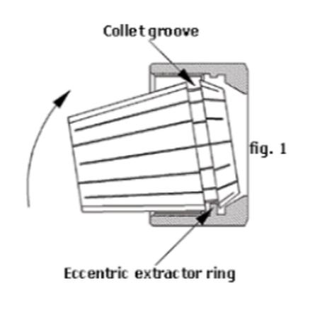 |
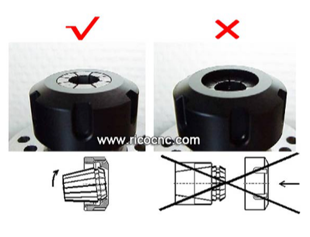
This typically occurs when the collet is placed in the collet pocket of the tool holder and then the nut is threaded on the tool holder. In a correct assembly, the collet will seat at the face of the collet nut.
The image below shows a correct assembly on the left and an incorrect assembly on the right.
Recognize Galling on Your ER Collet
| When trying to ensure the most rigid and accurate collet chuck assembly, don’t take chances. When in doubt, throw it out! Remember, the collet is designed to wear out and is the least expensive component in a collet chuck system. | 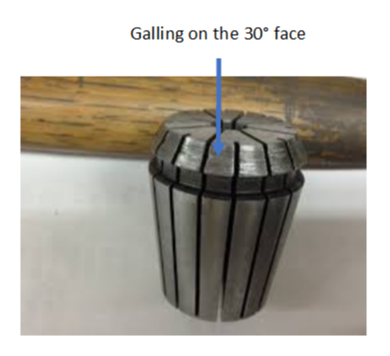 |
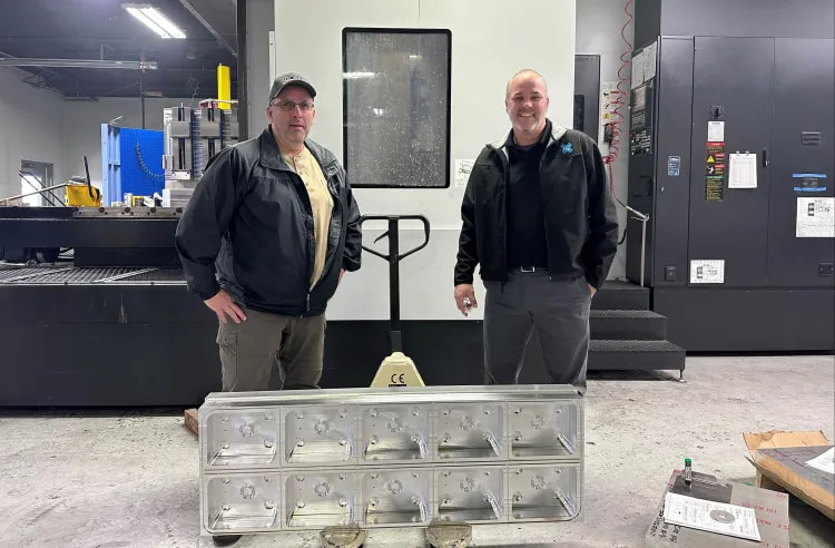
All Ross systems are designed to help processors streamline food manufacturing and packaging functions to improve quality, productivity, and food safety while minimizing waste.
With more than 50 years of industry expertise, Ross Industries has built an international reputation as one of the world’s finest food processing and packaging system providers. Employing approximately 100 staff, Ross Industries’ manufacturing plant is located in the city of Midland, Virginia, USA, with an estimate production area of 80,000-square-feet.

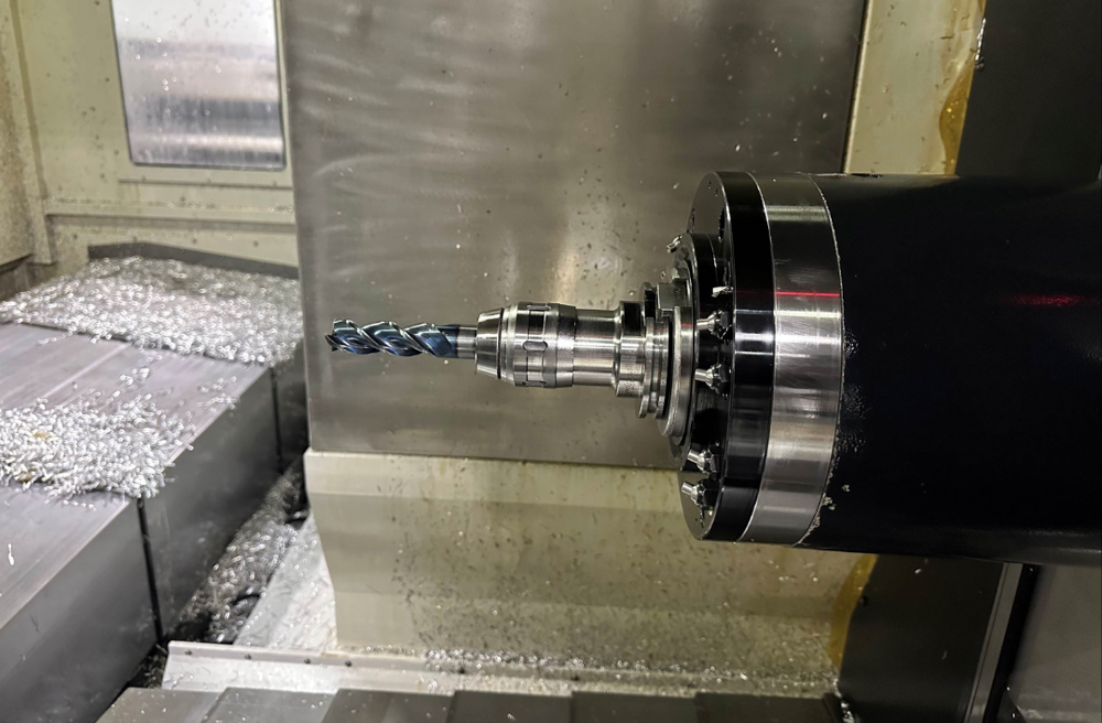
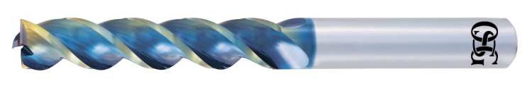
The AE-TL-N DLC coated carbide end mill is extremely effective for non-ferrous materials such as aluminum alloys that require welding resistance and lubricity. With excellent cutting sharpness, it is able to suppress burrs to achieve superb surface finish.
The AE-TL-N features a unique flute form to enable trouble-free chip evacuation and a large core design for high rigidity to prevent chattering. Its center cutting edge configuration enables the tool to be used for plunging. Furthermore, with the addition of OSG’s DLC-SUPER HARD coating, long tool life can be achieved. This end mill series is available in square, sharp corner edge and radius types to accommodate a wide range of applications.
By switching to the AE-TL-N, Ross Industries has reduced about 75 percent of cycle time on the upper chambers and is now on average achieving a 150 percent cycle time reduction on other aluminum parts.
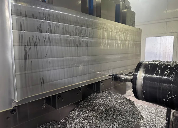
Taken in consideration of factors such as tool change time, machine cost, labor, etc., it is estimated that an annual cost savings of $183,000 can be gained. In addition to the upper chamber part, Ross Industries has also converted all of its aluminum end mills to OSG’s AE-TL-N series in various sizes.
For more information on OSG’s AE-TL-N DLC coated end mill for non-ferrous materials and Ross Industries
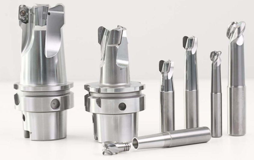
There are almost as many distinct variations of CNC tools as there are finished products that could be milled. If you are familiar with the functions these tools perform, it will be much more straightforward for you to select the ones appropriate for the project you are working on.
When it comes to the amount of time it takes and the quality of the work to be produced, choosing the appropriate cutting tool for your CNC milling machine, the material, and the type of milling can have a significant impact.
So here is a list of prominent milling tools utilized for CNC cutting.
The tool that should be utilized to cut also gets decided by the finalized design of the cut. Aside from these factors, specialists choose their tools based on how well they match the required speed with the desired finish.
Depending on the ultimate purpose of the completed product, one of these two considerations might take precedence over the other.
The top 7 milling tools for CNC cutting are:
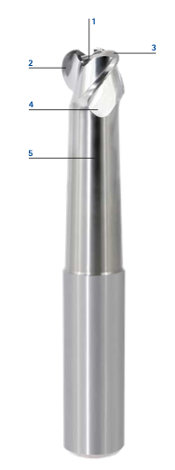
1. End Mills
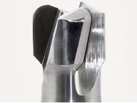
A center-cutting end mill is what's required to make a vertical cut. These mills can cut both the center and the margins of the workpiece.
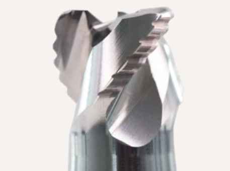
Non-center cutting end mills feature a hole in the middle of the tool and only contain cutting edges mostly along the ends of the mill. Since roughing end mills have fewer flutes than standard end mills, they are the tools of choice for making the initial cuts in a workpiece.
You will need finishing end mills with additional flutes to obtain a design similar to the part you want to produce. It will enable you to deliver a component that is cut with immense precision.
The tool employed on a project will vary depending on several factors, the most important of which is the number of flutes and the material of its composition.
The production of end mills typically involves the use of cobalt, high-speed steel, and carbide as raw materials. More details about the different types of mills (as per their material) are given below.
- Cobalt: Cobalt mills only contain eight percent cobalt, with the remaining construction built of steel. Cobalt mills can run at a pace that is 10 percent quicker than their counterparts.
- Carbide: The use of carbide end mills is recommended for finishing procedures.
- High-Speed Steel (HSS): It is the go-to material for mills of all kinds. It strikes an optimal balance between tool cost and service life. Since HSS has sufficient flexibility, it can be utilized for cutting iron and other materials.
End mills may perform a wide variety of cuts, the type of tool used depends on the type of cut being made:
- Face Milling - It is the process of just cutting into one surface of a material.
- Side Milling - It is used when chamfer mills are being employed to create beveled edges. To penetrate and smooth off the corner, you move the mill along the material's edge.
- Ramping - Ramping is a way of cutting at an angle into a surface, usually a diagonal cut through the material. It produces an angled toolpath while concurrently milling in the radial and axial directions. Toolpaths for ramping can be either circular or linear.
- Plunge Milling - It causes the end mill to plunge vertically into the workpiece. Like ramping, plunge milling necessitates using a center-cutting end mill to clean out the material from the hole's inside and perimeter.
- Slot Milling - Slot milling creates slots using an end mill to carve a groove in a material while cutting the edges on both sides simultaneously.
2. Face Mills
3. Twist Drills
4. Fly Cutters
5. Center Spotting Drills
6. Reamers
For reamers to work, a pilot hole of roughly the same diameter as the final product must first be bored.
7. Taps and Thread Mills
Thread mills are similar but can be employed to cut internal or external threads.
Concluding Remarks
About the Author
OptiMill-SPM: High Performance Mills for the High Volume Machining of Aluminium Structural Parts
11/15/2022
New machine generations that have sufficient drive power and the necessary spindle speeds make the high-performance machining of aluminum parts cost effective. MAPAL has developed a new range of aluminium roughing mills especially for these machines.
The OptiMill-SPM (structural part machining) high performance mill is equipped with a cutting edge that makes up 60%-80% of its diameter. This represents the maximum contact depth for the high-performance milling of aluminum.
Thanks to a highly positive cutting edge geometry and optimised chip flutes, the cutting force of PCD mills is reduced by up to 15%. Even when milling on standard machines, this reduction in cutting force results in more efficient machining parameters, and hence in improved performance.
The bottleneck form of the mill prevents the tool from bending during the machining process. Another advantage of this stable design
is the clearance that is created between the wall of the part and the mill shank. This prevents chips from scratching the wall of the part, particularly if it has deep pockets.
OptiMill-SPM tools with internal cooling are available in a solid carbide design with a diameter range of 6 to 32 mm or in a PCD design with a diameter range of 6 to 50 mm as part of the standard range. The range of products also includes variants with the well-known CFS replaceable head system.
OptiMill-SPM Roughing Tool Features in Detail
 OptiMill SPM Solid carbide design |
|
More Designs for Roughing
 OptiMill SPM | Solid carbide design with corrugated profile
|
 OptiMill Diamond SPM | PCD design
|
 CPMill SPM | Solid carbide design with replaceable head system
|
Speroni Tool Presetter: A Fabricator Finds Dramatic Time and Tool Cost Savings in an Unusual Place
12/15/2020

To keep up, Alpha Granite has invested in several advanced CNC machines, diminishing or altogether eliminating many of the laborious and time-consuming processes. Despite the technological advances, there was still a bottleneck that frustrated owners Denis and Sonia Phocas.
“Measuring tools in the stone industry was always a very laborious process,” explained Denis Phocas. “It’s archaic. You get wet, dirty and it takes a really long time. In reality, the process destroys tools because employees know the time and effort involved, so they tend to skip the necessary measuring intervals [ultimately cutting tool life roughly in half].
Dressing of the tools is also skipped, as this process needs to be done after a set amount of linear feet of work. In essence, the tools need to be measured and sharpened at set intervals to increase life.”
The traditional measuring process is manual. Measuring height and diameter to set up and inspect tools requires handheld instruments like calipers. Phocas explains how important accurate and sharp tools are to cutting stone profiles.
Since each profile requires several passes by six or seven different tools, each dependent on the accuracy, and more delicate than the one before. In other words, if the first tool isn’t dialed in right, the profile shape will be deformed, tools wear faster and the hours spent preparing them are wasted.
“Finding the center of one tool is hard enough,” he said. “Finding the center in relation to six others is very difficult.”
Phocas had heard about tool presetters, essentially a powerful microscope with a high-resolution monitor and basic computing power. It allows for precise inspection and measurement of tool edges. The process is relatively new to the stone industry and mostly limited to larger fabricators. As he explored further, Phocas began to understand why — only the big guys could afford them.
The presetters he saw from his distributers were big, expensive and, frankly, had more bells and whistles than a family-owned independent shop like Alpha Granite would need. Phocas recalled thinking, “It was such a major expense. Who needs to spend $60,000 on something you don’t need fully automated? There had to be a smaller solution.”
Phocas approached suppliers about entry-level options, but they continued pushing more expensive options. He got creative and found a metalworking supplier, Big Kaiser Precision Tooling in Hoffman Estates, IL, that might be able to help. The Speroni STP Essentia they offered featured a compact bench-top design, could work with any brand of router tools and handle the more complex tool profiles in stone cutting with ease. Most importantly, it was much less expensive than the other options he had found.
After working closely with a representative from Big Kaiser, even trying out an Essentia in his shop, Phocas was convinced and decided to purchase one. While there are significantly fewer types of tools used for profile cutting, this new capability and process would be an adjustment at first, starting with installation.
“I had never worked with one of these,” said Phocas. “It’s a precision tool. I wouldn’t call it daunting, but the process was interesting. We installed it in the workshop manager’s office because we wanted to keep it in a clean environment and because it’s got a computer hooked up to it. In the end, the installation process was pretty straightforward.”

“Once we got used to it, it was very easy,” said Phocas. “Our employees simply love the Essentia and now depend on it.”
The results have been undeniable. “The Essentia quickly tells you if a tool is out of shape,” explained Phocas. “I can prepare a set of tools in about 10 minutes, put them on the machine and start running. Whereas, with the old system it would take me anywhere between two to three hours, re-measuring and re-dressing while machines sat idle. We think our tool life has improved by 35 to 45 percent as well. It’s just phenomenal.”
Alpha Granite isn’t stopping there. In the near future, they’ll install software on their CNC routers that will precisely monitor the amount of linear feet each tool is working. This data will make tool recalibration even more streamlined. As things stand now, they have scheduled days for using the Essentia to recalibrate tools. With the new software, they’ll be able to recalibrate on-demand, so to speak, right when a tool has reached its manufacturer-recommended linear feet.
The addition of the Essentia has sparked dramatic process improvements. While presetters aren’t foreign to stonework, they aren’t all that common at fabrication shops like Alpha Granite. But if the results are any indication, other independent fabricators may want to get creative in their exploration of tool management options too.
The full story about Alpha Granite & Tile can be found in the April 2018 issue of Stone World or online at: www.stoneworld.com.
Shrink fit holders are the most accurate for TIR as the toolholder engages completely around round shank tools with a bore tolerance of -0.0001" to -0.0003". As high performance end mills have tightened shank tolerances to the same range of -0.0001" to -0.0003" they have used finer and finer grain grinding wheels which give the shanks a 'shiny' appearance.
Shiny means that the superfinished shank has a lower coefficient of friction. So, although the TIR is tighter, the shank is more "slippery". End mills traditionally had surface finish of about 8 μin on the tool shank. But that's changed. It's been recommended that tool shanks used in shrink fit holders should not have a finish finer than 16 μin. for optimum holding power, but tell that to the guy who just superfinished the end mill to a super cocncentric tolerance that you don't want it looking that good.
Everyone knows that the last thing you want is for the end mill to slip in the middle of a heavy cut or on the finishing pass of a high tolerance part. These 'hi performance' end mills, often times have higher helix angles which are great for ejecting chips but also create a higher pull out force on that slippery shank. And reducing the helix angle is not the answer.
We already know that the gripping pressure is a function of the interference between the tool shank and the shrink fit toolholder bore. Most shrink fit holders have a already bore surface finish of between 12 μin. and 16 μin. So they are ground to a very high tolerance and have about the same surface finish as the toolholder shank.
End mill manufacturers and machinist have tried a variety of methods over the years to stop the tools from pulling out. This has ranged from grit blasting the shank to rubbing chalk on the shank, but most everyone in the industry has felt that the problem really needs to be addressed by the longer life toolholder rather than the replaceable cutting tool.
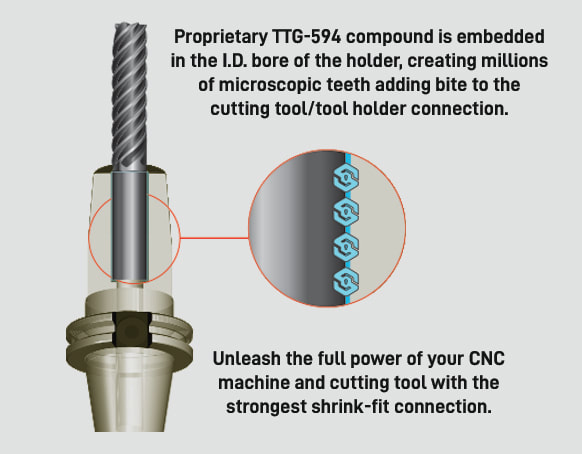
That's the problem that Techniks wanted to address. Techniks claims that their "proprietary non-slip TTG594 compound virtually fuses the tool shank with the shrink fit toolholder."
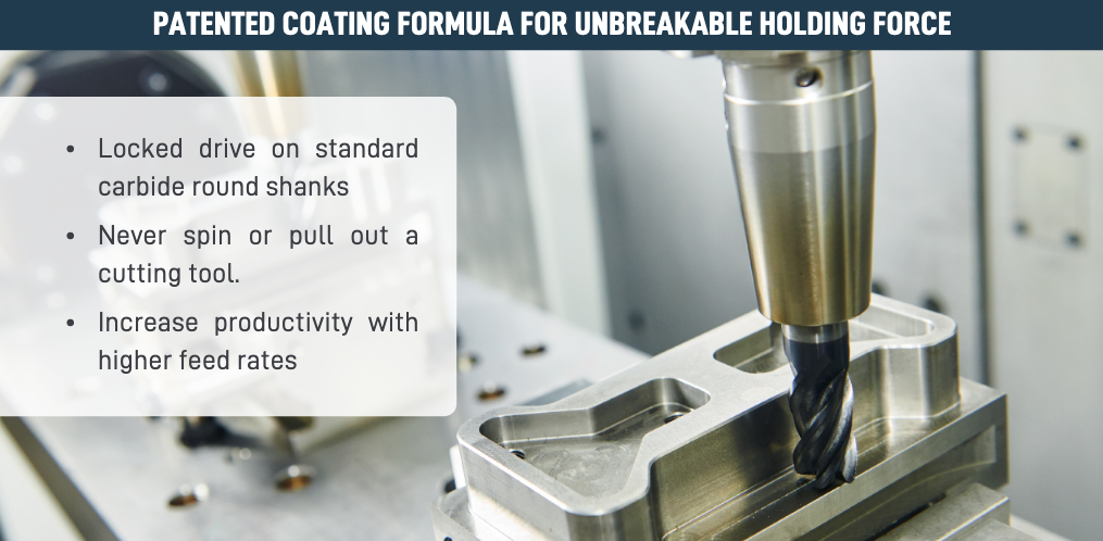
ShrinkLOCKED Toolholders eliminate cutting tool pull-out and provide 4X the friction drive force compared to un-treated shrink holders.
|  |
Techniks arrived at their 4x the holding power comes from torsion testing vs. a standard shrink fit toolholder. They used a ¾” carbide gage pin in a standard holder and found the torque at which the tool will spin in the bore.
They then tested the ShrinkLOCKED holder using the same test.
According to Greg Webb, at Techniks,
"We actually could not find the point at which the tool would spin in the ShrinkLOCKED holder as we broke the carbide gage pins at 4x+ times the torque of the standard holder. The holding power is greater, we just have not found a way to measure this, so we kept our claims conservative at 4x."

Technical Support Blog
We set up this special blog for the most commonly asked questions and machinist data tables for your easy reference.
If you've got a question that's not answered here, then just send us a quick note via email or reach one of us on our CONTACTS page here on the website.
Authorship
Our technical section is written by several different people. Sometimes, it's from our team here at Next Generation Tooling & at other times it's by one of the innovative manufacturer's we represent in California and Nevada.
Archives
July 2024
June 2024
May 2024
April 2024
March 2024
February 2024
January 2024
December 2023
November 2023
October 2023
September 2023
August 2023
July 2023
June 2023
May 2023
April 2023
March 2023
February 2023
January 2023
December 2022
November 2022
October 2022
September 2022
August 2022
July 2022
June 2022
May 2022
April 2022
March 2022
February 2022
December 2021
November 2021
October 2021
September 2021
August 2021
July 2021
June 2021
May 2021
April 2021
March 2021
February 2021
January 2021
December 2020
November 2020
October 2020
September 2020
August 2020
July 2020
June 2020
May 2020
March 2020
February 2020
January 2020
September 2019
August 2019
July 2019
June 2019
May 2019
March 2019
January 2019
September 2018
June 2018
April 2018
February 2018
December 2017
November 2017
October 2017
August 2017
June 2017
April 2017
March 2017
February 2017
January 2017
December 2016
November 2016
October 2016
August 2016
March 2016
February 2016
January 2016
November 2015
August 2015
July 2015
May 2015
April 2015
March 2015
November 2014
August 2014
July 2014
December 2013
November 2013
September 2013
July 2013
March 2013
December 2012
March 2012
November 2011
May 2011
March 2011
January 2011
December 2010
November 2010
October 2010
Categories
All
5th Axis
Aerospace
Allied Machine
Aluminum Oxide
Angle Head
AT3
Balance
Bellmouthed Hole
Big Daishowa
Big EWA Automatic Boring
Big Kaiser
BIG Plus
Blue Photon
Bone Screws
Boring Tool
Carbide
Carmex Precision
CBN
Centerline Deviation
Ceramic Black
Ceramic End Mill
Ceramic Inserts
Ceramic Oxide
Ceramic Whiskered
Ceramic White
Chamfer
Champion Tool Storage
Chip Breaking
Circular Saw
Class Of Fit
CNC Lathe Tooling
Collet
Collet Chuck
Collet ER
Collet TG
Composites
Covid-19
Deep Hole Boring
Deep Hole Drilling
Drilling
Dual Contact
Dyna Contact Gage
Dyna Force Tool
Dyna Test Bar
EMO
End Mill
Exotap
Facemill
Fixturing
Fretting
Gaylee Saw
Hard Turning
Heimatec
Helical Interpolation
Hohl Shaft Kegel
How Its Made
HSK A
HSK-A
HSK E
HSK-E
HSK F
HSK-F
HXL Tap
Hy Pro Tap
Hy-Pro Tap
IMTS
Jergens
Jergens OK-Vise
Kurt
Lang
Live Tooling
MA Ford
Maintenance Cart
Mapal
Martindale Saw
Material: Aluminum
Material: CFRP
Material: D2
Material: Hastelloy
Material: Inconel
Material: Peek
Material: Stone
Material Titanium
Material: VC 10
Material: VC-10
Metric Course Thread
Metric Fine Thread
Metric Thread Chart
Microconic
Micromachining
ModLoc
Modular
Mogul Bars
MPower
NextGen Tooling
No Go Too Loose
NTK
NTK HX5
On Site Training
OptiMill-SPM
OSG Tap & Die
Oversized Thread
Parlec
PCD
PCT Firm Hold
Platinum Tooling
Projection Length
Pull Studs
Reamer
Retention Knob
Rotary Toolholders
Rotary Toolholders BT
Rotary Toolholders CAT
Rotary Toolholders HSK
Rotary Toolholders Hydraulic
Rotary Toolholders Shrink
Rough Thread
Runout
Runout Axial
Runout Radial
Safe-Flex
Saw Selection
Short Tap Life
Sialons
Silicon Nitride
Smart Damper
Speed Increaser
SpeedLoc
Speroni STP Essntia
Spindle Mouth Wear
Surface Roughness Ra
Surface Roughness RMS
Swiss
Swiss Machining
Taper Wear
Tapping Feed
Tapping; Form
Tapping IPM
Tapping: Roll
Tapping RPM
Tapping Speed
Tap Tolerance
Technical Training
Technicrafts
Techniks USA
Thread Milling
Thread Whirling
T.I.R.
Tolerance
Toolchanger Alignment
Toolholder Taper
Tool Presetter
Torn Thread
Troubleshooting
UNC Thread Size
Undersized Thread
UNF Thread Size
Unilock
Vises
Washdown Tool
Workholding
 RSS Feed

About
|
© 2024 Next Generation Tooling, LLC.
All Rights Reserved Created by Rapid Production Marketing
|
