|
By John Zaya, Product Specialist, BIG DAISHOWA—Americas  As the title implies adjusting screws, also known as back-up screws, stop screws and preset screws, are not just a simple set screw. They are a screw with a purpose--three actually. The first is to provide a fixed stop for a cutting tool to rest against during tool changes. This allows an operator to save time as they do not have to pull out a ruler, setting jig, etc. to reassemble the cutter into a holder. A secondary purpose of the adjusting screw is to assist the tool holder in keeping the cutter from being pushed up into the holder if the cutting loads increase to the point where the tool may slip up into the holder. The third is to offer sealing for coolant-through tools. Expected repeatability of cutting tool length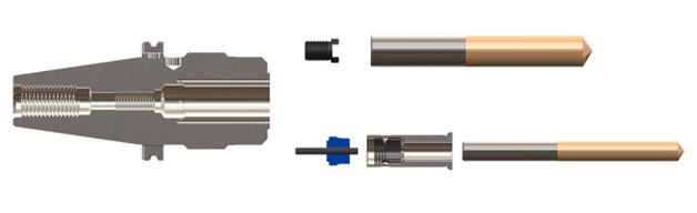 When an old cutter is swapped out and a new one put in its place, the repeatability of this process will vary based on a few parameters such as cleanliness and the OEM cutting tool overall length tolerances. Cleaning the clamping bore or collet of a holder provides better runout repeatability which should be old news to everyone, but if old coolant and contaminants are not removed, they would get jammed between the end face of the shank and the adjusting screw, affecting the length setting. Cutting tool overall length tolerances may also vary from one OEM to another. We have seen them range from ±.3mm to ±.5mm (±.012” to ±.019”). Others may be tighter or looser. Most modern machining centers come with tool length offset measurement systems which will provide the final precise gage length of a tool assembly. With the rough position provided by the adjusting screw, the machine operator can continue working and does not need to worry about tool clearances and stick outs. Forms of adjusting screws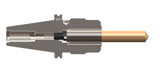 The clamping mechanism of the holder also affects the length repeatability. Both hydraulic chucks and milling chucks are radial clamping systems, whereas a tapered collet is drawn down into a taper by a threaded nut. This draw down causes the cutter to be drawn down as well. For this we have two types of adjusting screws:
Option for adjustable reduction sleeves for MEGA DS/HMC Milling chucks also have a second type of adjustment screw option that can be built into the back end of a reduction sleeve. As cutting tool diameters get smaller, the length of the shank also gets shorter. As such, the end face of the shank may not reach the HMA adjusting screw when installed it the body of the holder. The AC Type Collet adjuster screws into the back end of the reduction sleeve where the shank the tool can easily be reached. Warning on holders that cannot support adjusting screwsIt is always recommended to consult the tool holder catalog or technical documentation to ensure that a holder can support an adjusting screw. Some holders are very short or have very deep internal features that may not allow for the use of any adjusting screw. In those cases, a depth setting ring or collar on the shank of the cutting tool may be an acceptable alternative.
Caution should be used on shrink-fit holders. Thermal expansion/contraction occurs in all three axes, so as the body of a shrink-fit holder cools down it will draw the cutter down jamming onto the adjusting screw. This could lead to damage to the screw, the holder or the cutter.
0 Comments
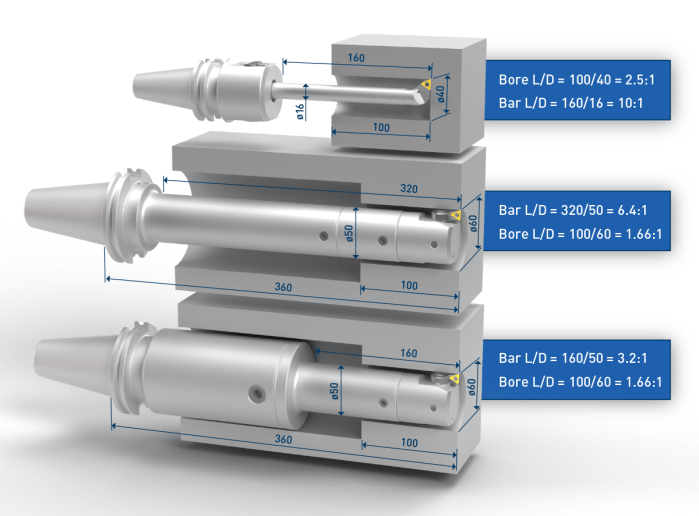 The L:D ratio of a tool assembly is calculated by using the length of the bar (or body) of a tool assembly and the diameter of the tool, not the workpiece bore diameter and depth.
To expand on this concept, we see in the first configuration below the Ø16mm bar is sticking out 160mm which is a 10:1 although the bore is only a 2.5:1. In some applications this extra reach is needed to get around a fixture or a feature of the part. However, in those cases where it is not needed, decreasing the overhang by 55mm means the new L:D of 105:16 is 6.5:1. This alone would represent approximately 10x increase in cutting speed by increasing from 20mm/min vs. 200mm/min. The use of modular reductions has also been found to be a good strategy to improve tool performance. Comparing the lower two assemblies below, the middle assembly uses the same connection size for the length of the tool, ignoring the larger access diameter, and results in a 6.4:1 ratio. When a shank with a larger connection size is used along with a modular reduction, the ratio is halved, and provides a 350% productivity improvement (14mm/min to 50mm/min). In all cases, reducing the L:D ratio provides an improvement in speed which then provides longer tool life, better surface finish and size control of the bore. 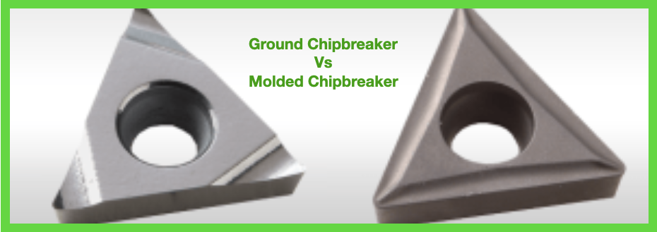 A common question asked for boring operations is when would I use a ground chip-breaker vs. a molded chip-breaker? A ground chip-breaker is recommended for chip control issues. The high-positive rake angle will help to make shorter chips, and the chip groove orientation forces the chips forward to more easily evacuate them from the bore, especially when used with high-pressure coolant through the tool. Ground chip-breaker inserts also provide lower cutting forces, so they are better suited for deep-boring or long-reach applications, and other situations where part or tool stability may not be optimal. Ground chip-breakers are also recommended for tight-tolerance applications where stock allowance is typically light for the final size pass. A molded chip breaker is recommended for stable applications in short-chipping materials. Because these situations don’t require a super-sharp edge for cutting the material, these inserts hold their edge longer for better tool life, and in most cases are less expensive. A Primer on Types of Chips
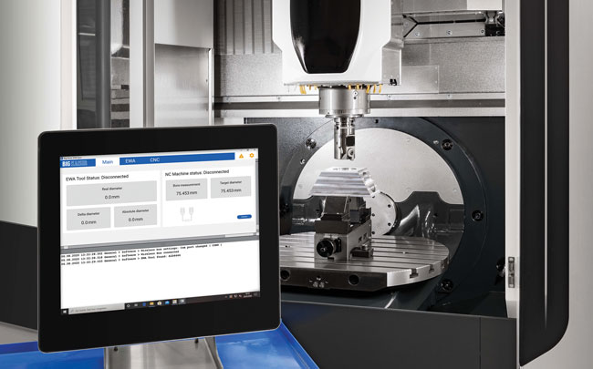 The Big Kaiser EWA Automatic Fine Boring System can be integrated in three primary configurations: fully integrated, PC control, or tablet control. (Courtesy: Big Daishowa) Hoffman Estates, IL - The BIG KAISER EWA Automatic Fine Boring System from BIG DAISHOWA performs closed-loop boring operations without a human operator. This breakthrough eliminates the need to stop the spindle to manually adjust the boring tool, which results in considerable time savings. Also, eliminating human interaction reduces cost, improves accuracy, and minimizes scrap. The adjustment range of this fine boring head allows for the handling of multiple bore sizes with the same tool and ensures a repeatable boring process.
The EWA fine boring head is available in two sizes, one with a boring range of Ø2.677"-5.276" (Ø68-134mm) and the other with a range of Ø.394"-2.126" (Ø10-54mm). EWA kits are also available for each of these head sizes. These can include inserts, insert holders, a controller, antenna and protective case. The EWA can be used on machines with BT/BBT30-40-50, CV/BCV(SK)40-50, BIG CAPTO 5-6-8 and HSK-A63-80-100-125 spindles. The Automatic Fine Boring System can be integrated in three primary configurations: fully integrated, PC control, or tablet control. Fully Integrated A fully integrated system has the EWA control software running directly on the machine tool control via an app or technology cycle, requiring no external control device. The fully integrated system can only be integrated on new machine tools. PC Control For legacy machines, a PC interface between the machine tool and the EWA can provide a fully automated, closed-loop control cycle. Commands are sent from the machine tool to the EWA, automatically adjusting the tool in synchronization with the machining process. The PC acts as a synchronization interface between the machine tool and the EWA. It stops the machining cycle after the touch probe makes a measurement, reads the result and sends the corresponding adjustment value to the EWA. After the EWA has been adjusted, the PC notifies the machine tool to continue the process. Tablet Control The EWA can also be operated as a standalone tool, controlled manually with the BIG KAISER app on a tablet or smartphone. This enables the option to measure bores using an in-machine probe or manually, and to make fast adjustments in the app. Adjustments also can be done semi-automatically, where the head will move to pre-entered diameter values after a stoppage. To see the EWA Automatic Fine Boring System and other innovations from BIG DAISHOWA, visit booth #431610 at IMTS. 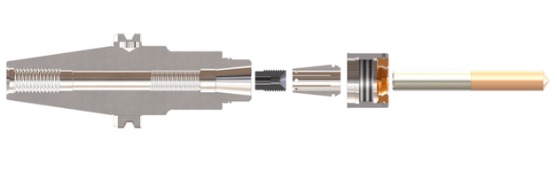 As the title implies adjusting screws, also known as back-up screws, stop screws and preset screws, are not just a simple set screw. They are a screw with a purpose--three actually. The first is to provide a fixed stop for a cutting tool to rest against during tool changes. This allows an operator to save time as they do not have to pull out a ruler, setting jig, etc. to reassemble the cutter into a holder. A secondary purpose of the adjusting screw is to assist the tool holder in keeping the cutter from being pushed up into the holder if the cutting loads increase to the point where the tool may slip up into the holder. The third is to offer sealing for coolant-through tools. 1. Expected repeatability of cutting tool lengthWhen an old cutter is swapped out and a new one put in its place, the repeatability of this process will vary based on a few parameters such as cleanliness and the OEM cutting tool overall length tolerances. Cleaning the clamping bore or collet of a holder provides better runout repeatability which should be old news to everyone, but if old coolant and contaminants are not removed, they would get jammed between the end face of the shank and the adjusting screw, affecting the length setting. Cutting tool overall length tolerances may also vary from one OEM to another. We have seen them range from ±.3mm to ±.5mm (±.012” to ±.019”). Others may be tighter or looser. Most modern machining centers come with tool length offset measurement systems which will provide the final precise gage length of a tool assembly. With the rough position provided by the adjusting screw, the machine operator can continue working and does not need to worry about tool clearances and stick outs. 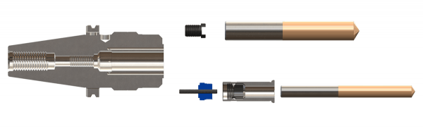 2. Forms of adjusting screwsThe clamping mechanism of the holder also affects the length repeatability. Both hydraulic chucks and milling chucks are radial clamping systems, whereas a tapered collet is drawn down into a taper by a threaded nut. This draw down causes the cutter to be drawn down as well. For this we have two types of adjusting screws: HMA/HDA solid type and NBA rubberized type. The solid type is a one-piece steel construction part, whereas the rubberized type has a rubber padded conical pocket that absorbs the axial travel of the cutter shank as the collet is clamped. 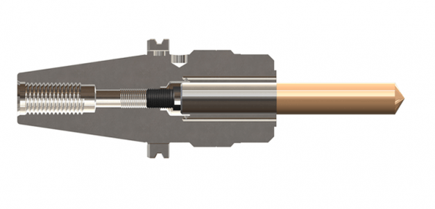 3. Option for adjustable reduction sleeves for MEGA DS/HMCMilling chucks also have a second type of adjustment screw option that can be built into the back end of a reduction sleeve. As cutting tool diameters get smaller, the length of the shank also gets shorter. As such, the end face of the shank may not reach the HMA adjusting screw when installed it the body of the holder. The AC Type Collet adjuster screws into the back end of the reduction sleeve where the shank the tool can easily be reached. 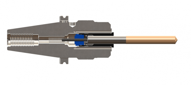 4. Warning on holders that cannot support adjusting screwsIt is always recommended to consult the tool holder catalog or technical documentation to ensure that a holder can support an adjusting screw. Some holders are very short or have very deep internal features that may not allow for the use of any adjusting screw. In those cases, a depth setting ring or collar on the shank of the cutting tool may be an acceptable alternative.
Caution should be used on shrink-fit holders. Thermal expansion/contraction occurs in all three axes, so as the body of a shrink-fit holder cools down it will draw the cutter down jamming onto the adjusting screw. This could lead to damage to the screw, the holder or the cutter. John Zaya, Product Specialist, explains the concepts behind the UNILOCK Zero-Point workholding system. He also discusses base pallets and options for 5-axis machines. Chapters: 0:00 Introduction 0:13 Basic Concepts 0:52 Features of the UNILOCK Clamping Knob 1:50 UNILOCK 5-Axis Program BIG DAISHOWA is a different kind of tooling partner. Our mission is to find the best of the best and deliver it to our customers with a personal commitment to helping them install truly efficient solutions. We have exceptionally high standards for the products we represent. The result is an all-star line-up of products that deliver true and measurable performance advantages. Products that are engineered to exacting standards and then manufactured with materials and craftsmanship that enable superior performance.
|
Technical Support BlogAt Next Generation Tool we often run into many of the same technical questions from different customers. This section should answer many of your most common questions.
We set up this special blog for the most commonly asked questions and machinist data tables for your easy reference. If you've got a question that's not answered here, then just send us a quick note via email or reach one of us on our CONTACTS page here on the website. AuthorshipOur technical section is written by several different people. Sometimes, it's from our team here at Next Generation Tooling & at other times it's by one of the innovative manufacturer's we represent in California and Nevada. Archives
March 2024
Categories
All
|
 RSS Feed

About
|
© 2024 Next Generation Tooling, LLC.
All Rights Reserved Created by Rapid Production Marketing
|
