|
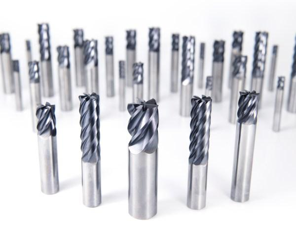
by Peter Jacobs, via OSG USA blog There are almost as many distinct variations of CNC tools as there are finished products that could be milled. If you are familiar with the functions these tools perform, it will be much more straightforward for you to select the ones appropriate for the project you are working on. When it comes to the amount of time it takes and the quality of the work to be produced, choosing the appropriate cutting tool for your CNC milling machine, the material, and the type of milling can have a significant impact. So here is a list of prominent milling tools utilized for CNC cutting. Different types of CNC milling tools make it feasible to achieve the highest level of product customization. While cutting into and shaping different types of materials, several tools are employed. The tool that should be utilized to cut also gets decided by the finalized design of the cut. Aside from these factors, specialists choose their tools based on how well they match the required speed with the desired finish. Depending on the ultimate purpose of the completed product, one of these two considerations might take precedence over the other. The top 7 milling tools for CNC cutting are: 1. End MillsThere are numerous kinds of end mills, each of which is designed for a particular kind of cutting. All end mills cut at an angle of ninety degrees. A center-cutting end mill is what's required to make a vertical cut. These mills can cut both the center and the margins of the workpiece. Non-center cutting end mills feature a hole in the middle of the tool and only contain cutting edges mostly along the ends of the mill. Since roughing end mills have fewer flutes than standard end mills, they are the tools of choice for making the initial cuts in a workpiece. You will need finishing end mills with additional flutes to obtain a design similar to the part you want to produce. It will enable you to deliver a component that is cut with immense precision. The tool employed on a project will vary depending on several factors, the most important of which is the number of flutes and the material of its composition. The production of end mills typically involves the use of cobalt, high-speed steel, and carbide as raw materials. More details about the different types of mills (as per their material) are given below.
End mills may perform a wide variety of cuts, the type of tool used depends on the type of cut being made:
2. Face MillsThis tool is primarily used to create a level surface on a solid portion of the material. As the first step in milling, this is often performed on the top of the stock to smooth it out. The cutter inserts in a face mill's sole body can be changed for specialized cutting tasks. You would require more cutters to remove metal at a faster rate. 3. Twist DrillsDrill bits resemble end mills in that they have a conical cutting tip on the end of a shaft with one or even more flutes. Twist drills are often made from solid carbide or High-Speed Steel (HSS). The drill's hardness, wear resistance, and lifespan can be improved by applying a gold-colored coating, such as TiN. 4. Fly CuttersFly cutters are considered the best to create a fantastic surface finish. The clockwise motion of these cutting tools produces a mirror-like finish on the material. 5. Center Spotting DrillsThese stocky tools first construct a precise conical hole to avoid the drill bit from drifting during a cutting operation and end up drilling the hole at an incorrect site. Screw clearance holes and counterbores can be drilled with the same tool thanks to multi-function drills that spot and countersink. 6. ReamersReamers are mainly utilized to enlarge the existing holes in compliance with the tolerance while providing a superior surface finish. They help you ensure the accuracy of the roundness and diameter of a drilled hole. For reamers to work, a pilot hole of roughly the same diameter as the final product must first be bored. 7. Taps and Thread MillsTaps are tools used to cut threads into the interior of a material. Yet not every thread is produced by a cutting procedure. By applying pressure, Roll Form taps get inserted into holes, and the surrounding material is shaped to fit them. Thread mills are similar but can be employed to cut internal or external threads. Concluding RemarksThe key to successfully machining products and components is selecting the appropriate CNC tool. Learn how each one functions, and keep in mind the use of the most beneficial ones in your manufacturing facility. About the AuthorPeter Jacobs is the Senior Director of Marketing at CNC Masters. He is actively involved in manufacturing processes and regularly contributes his insights for various blogs in CNC machining, 3D printing, rapid tooling, injection molding, metal casting, and manufacturing in general.
1 Comment
We are very excited to announce that we are now able to offer on-site technical training to YOUR machinists at YOUR location! This is offered at no charge to customers who use any of the manufacturer's whom we represent in California and Nevada. However, just because you don't purchase things from us, don't feel left out! We also offer on-site topic specter training on any of the following topics for $150/hour. Each presentation lasts about 2 hours. The presentations last approximately 45-60 minutes with the remaining time for Q&A and discussion about unique applications in your facility.  Training Classes Available: Machining 101
Advanced Part Manufacturing:
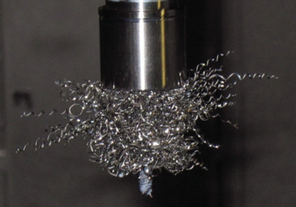
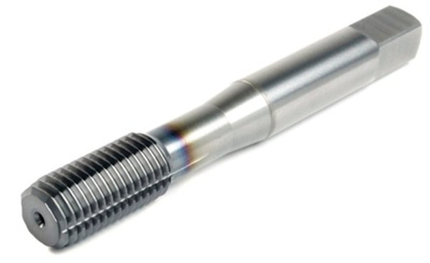
by David Aly, Aerospace Specialist, OSG Tap & Die Just because you’ve tried one forming tap, doesn’t mean you’ve tried them all. We had the recent opportunity to prove that OSG forming taps are better than the rest. As a supplier of custom fabricated metal products and machinery, one of our customers approached us wanting to get better chip control during their tapping operation. Located in Winona, Mississippi, they have a 92,500 square foot manufacturing facility for producing fuel tanks, hydraulic tanks and custom designed machining fixtures. After discussing the customer’s chip control needs, I recommended OSG’s EXOTAP® NRT® Forming Tap, a more stable, thread rolling tap that makes threads by compressing the work material without creating chips. Because no chip is produced, breakage due to chip packing and bird nesting is eliminated. The EXOTAP® NRT® also has significantly reduced friction resistance because of its special threading design and surface treatment. Made from VC-10 Powdered Metal High Speed Steel, this forming tap has a longer tool life when tapping difficult to machine materials like carbon steels, alloy steels, stainless steels and aluminum alloy. Initially, the shop foreman, Mr. William Smith, was hesitant about using a forming tap due to a bad experience with a competitor’s brand. After I showed William a presentation and a chip flow demonstration video, he was willing to give our forming tap a chance. We approached his staff with OSG’s EXOTAP® NRT® Forming Tap in hand. After explaining the test with the operator and reiterating that there will be no chips, we began the trial. A few days later, I called to check in on their progress. William enthusiastically explained that he was still running the same tap. He had lost count of the number of holes produced but assured me that it was well over 1,000 holes! After such a successful run with the first test tap, he purchased more of the test size, now truly convinced that all forming taps are not created equal.
The tolerance of the tap should be manufactured as close as possible to the finished internal thread tolerance.
This practice ensures that the threads produced will comply to the gage tolerances providing that the working conditions such as machine, chucking tools, and workpiece match the application. H LImits Explained
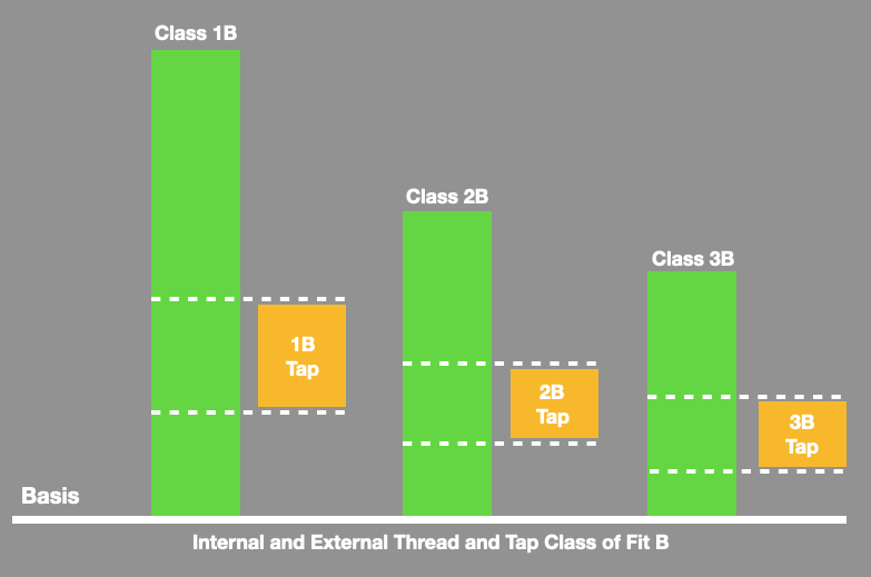
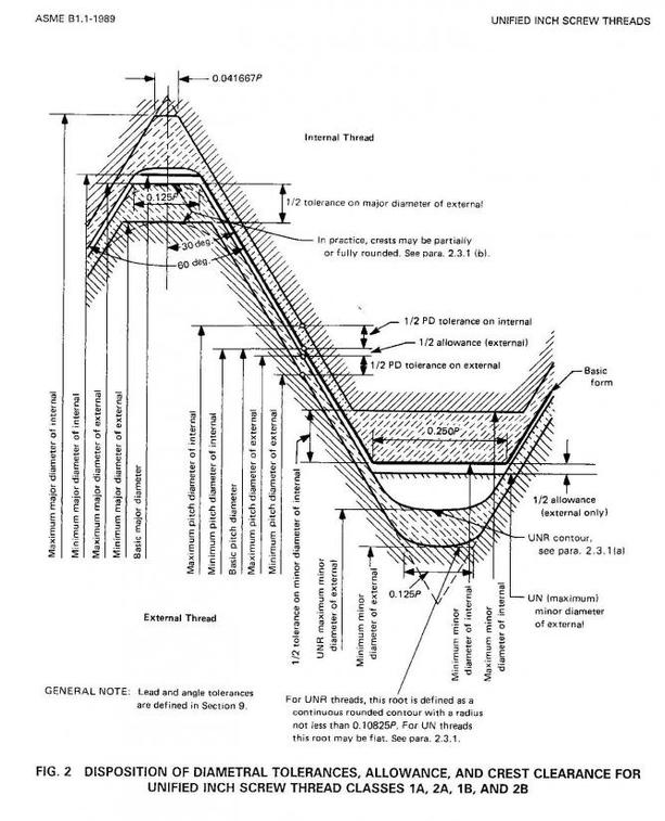
H limits are used to properly size a tap for the threaded hole to be produced. They are selected based upon the tolerance required for the part. These tolerances are defined by the symbols class 1B, 2B, or 3B.
The sizes of a 2B and a 3B tap are different. The 2B tap is smaller in size. It has an outside diameter of 0860 inches. The 3B tap is larger by .0130 inches, making its outside diameter .0990 inches. As the sizes progress up the tap scale, it increases in size by .0130 inches in outside diameter. Other types of taps, such as hand or fractional taps, increase in increments of 1/4 of an inch and referenced not as a number, but the size in inches
Selecting a H Limit on a tap
Once the class of thread and part tolerance has been defined, an H limit is selected to produce a thread that is within the minimum and maximum limits for that class if fit. These limits are the same as the Go and Not Go thread plug gage dimensions.
The goal is to select a tap with an H-limit that is near the middle of the part tolerance. For instance, if the total tolerance was .005", the tap should be approximately .0025" larger than the minimum limit of the part and .0025" smaller than the maximum. In order to handle the widest variety of tapping conditions, the "40% rule" is commonly applied. Using this rule, the tap is selected at 40% of the part tolerance. For instance, if the part tolerance is .005", multiplying .005" by 0.40 equals .002". Thus, the tap would be .002" larger than the minimum limit of the part or Go thread gage. With the position of the tap in relationship to the part tolerance established, the selection of an H limit number, such as H3, H4, H5, etc. is possible. H limits are a sequence of size "steps" in .0005" increments beginning at the minimum size limit of the part, starting with H1. In other words, an H1 limit is one .0005" increment larger than the minimum limit or Go gage, an H2 is two .0005" increments (or .001) larger than the minimum limit, an H3 is three .0005" increments (or .0015") and so on. In the example above, a tap that is .002" larger than minimum limit, is four .0005" increments larger, or an H4. This would be the tap H limit recommendation for this tolerance.
Taps are general marked with the appropriate tolerance class for their intended use. The U.S. GH thread class numbers are not marked on the tap.
Tolerances for the various GH numbers are shown in the chart below Classification for the tolerance 1B can be provided upon request. Taps for cast iron and titanium tapping are designed one GH class higher to provide better tool life. |
Technical Support BlogAt Next Generation Tool we often run into many of the same technical questions from different customers. This section should answer many of your most common questions.
We set up this special blog for the most commonly asked questions and machinist data tables for your easy reference. If you've got a question that's not answered here, then just send us a quick note via email or reach one of us on our CONTACTS page here on the website. AuthorshipOur technical section is written by several different people. Sometimes, it's from our team here at Next Generation Tooling & at other times it's by one of the innovative manufacturer's we represent in California and Nevada. Archives
July 2024
Categories
All
|
||||||||||||||||||||||||||||||||||||||||||||||||||||||||||||||||||||||||||||||||||||||||||||||||||||||||||||||||||||||||||||||||||||||||||||||||||||||||||||||||
About
|
© 2024 Next Generation Tooling, LLC.
All Rights Reserved Created by Rapid Production Marketing
|

 RSS Feed
