 The number of flutes on a carbide end mill significantly influences its performance across various machining applications. How many flutes do you need? The simple answer: It depends. Obviously there are a quite a number of other factors that impact an end mills performance such as helix angel, edge prep, gullet depth and radius. We can't tackle everything in this article, but hopefully this helps you get a better understanding of why there are different numbers of flutes on end mills. Below is an overview of the advantages and disadvantages associated with end mills featuring different flute counts, along with recommendations for materials based on ISO 513 categories (P, M, K, N, S, H) Single Flute End Mills
2-Flute End Mills
3-Flute End Mills
4-Flute End Mills
5-Flute End Mills
6-Flute End Mills
7-Flute End Mills
8-Flute End Mills
0-Flute End Mills
Advantages of Higher Flute Counts in |
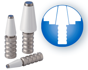
| First, angle the collet so the extraction groove seats with the eccentric extraction ring in the collet nut as shown below. Next, while holding the collet and nut together, place the assembly in the tool holder and begin tightening the nut. | 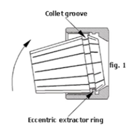 |
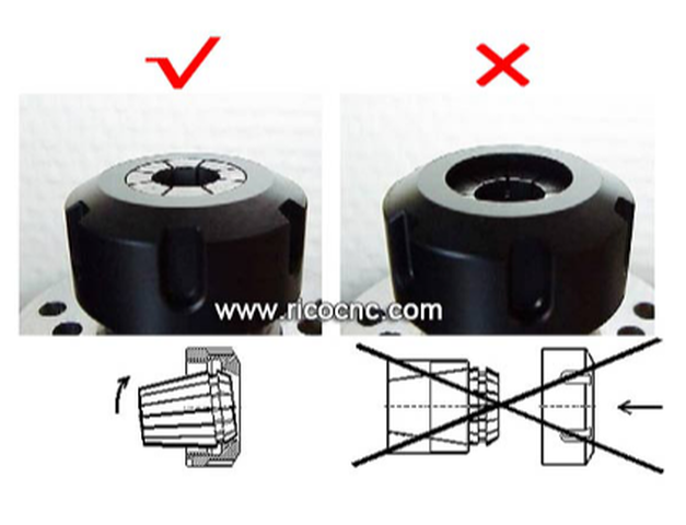
This typically occurs when the collet is placed in the collet pocket of the tool holder and then the nut is threaded on the tool holder. In a correct assembly, the collet will seat at the face of the collet nut.
The image below shows a correct assembly on the left and an incorrect assembly on the right.
Recognize Galling on Your ER Collet
| When trying to ensure the most rigid and accurate collet chuck assembly, don’t take chances. When in doubt, throw it out! Remember, the collet is designed to wear out and is the least expensive component in a collet chuck system. | 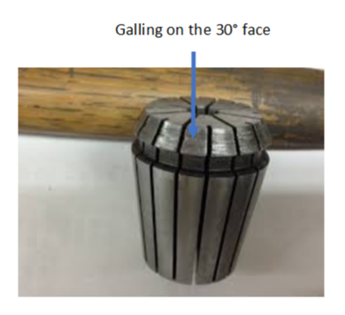 |
That means that a 1/8” tool with a 0.00019” chip load per tooth will lose 40% of its tool-life with a run-out of less than 0.0001”.
Excessive and inconsistent run-out from a properly setup ER collet chuck assembly typically occurs due to friction build-up between the 30° face of the collet and the collet nut.
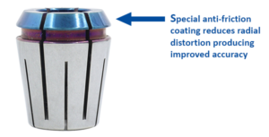
| As the collet nut presses down and turns against the 30° face of the collet, the collet face will tend to twist with the collet nut, distorting the shape of the collet. This radial distortion negatively affects tool run-out sine the collet bore is not longer straight. Parlec’s new P3 ER collets have a special anti-friction coating on the 30° face that dramatically reduces friction at this critical connection. | 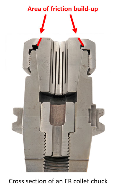 |
- Improved tool runout
- Longer tool-life
- Less frequent tool changes
- Improved surface finishes
Other Parlec P3 collet advantages:
- 3 micron T.I.R
- Fewer slots that standard collets making them more rigid – in the cut!
- Special slotting seal for coolant up to 2,000 PSI
Don’t throw away you ER collet chucks to improve accuracy
Try Parlec P3 collets and supercharge your ER collet system.
Boring Bars
Solid boring bars
Typically made of carbide for finishing or heavy metal for roughing, solid boring bars have dense structures that make for a more stable cut as axial force is applied.
Damping bars
When cutting speeds are compromised, or surface finishes show chatter in a long-reach boring operation, damping bars are an option. They have integrated damping systems. Our version, the Smart Damper, works as both a counter damper and friction damper so that chatter is essentially absorbed.
Boring Heads
Rough boring heads
Once a bore is started with a drill or by another method, rough boring heads are the choice for removing larger amounts of material. They are built more rigid, to handle the increased depths of cut, torque and axial forces needed to efficiently and consistently make the passes to remove materials.
Fine boring heads
Fine boring heads are best used for more delicate and precise removal of material that finishes the work the rough boring head started. They are often balanced for high-speed cutting since that’s the best approach for reaching exact specifications.
Twin cutter boring heads
Most boring heads feature one cutter that cuts as its feed diameter is adjusted by the machine. There are twin cutter boring heads that can speed up cutting and add versatility. For example, the Series 319 and other BIG KAISER twin cutter boring heads include two cutters that can perform balanced or stepped cutting without additional accessories or adjustments by switching the mounting locations of the insert holders that have varied heights.
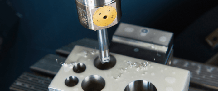
Digital boring heads
Traditionally, adjusting boring heads has been painstaking and time-consuming, especially when it’s done in the machine. It’s easy to make mistakes when maneuvering to read the diameter dial and adjusting it to the right diameter. Digital boring heads have a LED that makes precise adjustments much easier.
Starter Drills
Specialty boring heads
Back boring and face grooving heads, as well as chamfering insert holders, are available for some of the most common secondary operations, after a hole is bored. We produce specific heads with cutters at the appropriate angles so each of these operations can be done without manually moving the part, changing the tool or adjusting the cutter angle.
Modular boring tools
Since limiting length-to-diameter ratios is so crucial to boring success, it’s extremely valuable to be able to make your tooling assembly as short as possible. Our modular components are based on a cylindrical connection with radial locking screw that allows for the ideal combination of different kinds of shanks, reductions and extensions, bars, ER collet adapters and coolant inducers.
Looking for some help finding the right boring equipment for your next job or new machine? Our engineers are here to help. Get in touch with us here.
It makes regular inspection and spindle maintenance critical to getting the most out of your equipment and maintain process efficiency. These three accessories, the Dyna Contact Taper Gage, the Dyna Test Bar and the Dyna Force Measurement Tool, can help you perform this maintenance easily without eating into valuable spindle time.
Dyna Contact Taper Gage
 Dyna Contact CNC Spindle Taper Gage | Spindle taper protection The Dyna Contact taper gage makes verifying taper accuracy simple. All the operator must do is apply blue dye to the ceramic gage, insert it in the machine spindle and remove it. A quick visual check will reveal any improper contact points inside the taper. |
Dyna Test Bar
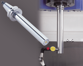 Dyna CNC Spindle Test Bar | Static accuracy inspection Another way to ensure your spindle bearings are good and ensure quality control is to measure its static accuracy. Using something like our Dyna Test bar, which inserts into the taper and extends out, is one way to do this. |
Dyna Force Measurement Tool
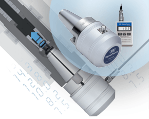 Dyna Force CNC Spindle Force Measurement Tool | Retention force verification Finally, in the machinery category, let’s talk retention force. The clamping mechanism in your spindle reduces chatter while ensuring rigidity and reliability. Like any other mechanism this can wear, making regular inspection a smart idea. |
Shrink fit holders are the most accurate for TIR as the toolholder engages completely around round shank tools with a bore tolerance of -0.0001" to -0.0003". As high performance end mills have tightened shank tolerances to the same range of -0.0001" to -0.0003" they have used finer and finer grain grinding wheels which give the shanks a 'shiny' appearance.
Shiny means that the superfinished shank has a lower coefficient of friction. So, although the TIR is tighter, the shank is more "slippery". End mills traditionally had surface finish of about 8 μin on the tool shank. But that's changed. It's been recommended that tool shanks used in shrink fit holders should not have a finish finer than 16 μin. for optimum holding power, but tell that to the guy who just superfinished the end mill to a super cocncentric tolerance that you don't want it looking that good.
Everyone knows that the last thing you want is for the end mill to slip in the middle of a heavy cut or on the finishing pass of a high tolerance part. These 'hi performance' end mills, often times have higher helix angles which are great for ejecting chips but also create a higher pull out force on that slippery shank. And reducing the helix angle is not the answer.
We already know that the gripping pressure is a function of the interference between the tool shank and the shrink fit toolholder bore. Most shrink fit holders have a already bore surface finish of between 12 μin. and 16 μin. So they are ground to a very high tolerance and have about the same surface finish as the toolholder shank.
End mill manufacturers and machinist have tried a variety of methods over the years to stop the tools from pulling out. This has ranged from grit blasting the shank to rubbing chalk on the shank, but most everyone in the industry has felt that the problem really needs to be addressed by the longer life toolholder rather than the replaceable cutting tool.
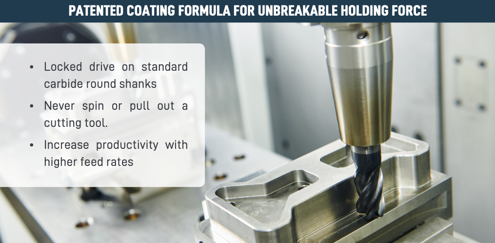
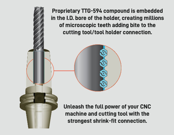
That's the problem that Techniks wanted to address. Techniks claims that their "proprietary non-slip TTG594 compound virtually fuses the tool shank with the shrink fit toolholder."
ShrinkLOCKED Toolholders eliminate cutting tool pull-out and provide 4X the friction drive force compared to un-treated shrink holders.
|  |
Techniks arrived at their 4x the holding power comes from torsion testing vs. a standard shrink fit toolholder. They used a ¾” carbide gage pin in a standard holder and found the torque at which the tool will spin in the bore.
They then tested the ShrinkLOCKED holder using the same test.
According to Greg Webb, at Techniks,
"We actually could not find the point at which the tool would spin in the ShrinkLOCKED holder as we broke the carbide gage pins at 4x+ times the torque of the standard holder. The holding power is greater, we just have not found a way to measure this, so we kept our claims conservative at 4x."

If you understand why a long tool holder behaves the way it does, you’ll know that there are ways to fight back against this bending. Every machinist knows that short and stubby holders are more resistant to deflection than long and slender holders. You’ve also probably heard that, if possible, you’ll want most of your cutting forces to be axial rather than radial.
Not only does this fight chatter in operations like boring, but your spindle also is better equipped to handle loads in this axis. However, these options aren’t always going to be on the table, especially in unavoidable long-reach situations and many milling operations.
In this constant battle with tool deflection, much time and effort has been spent designing shorter holders, stiffer tools, and clever anti-vibration geometry and materials. But oftentimes, the body diameter(s) of the holder can be overlooked as a means of increasing rigidity, especially in situations where it is all you have to work with. This is a serious shame, as you’ll soon discover.
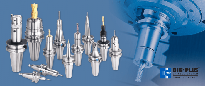
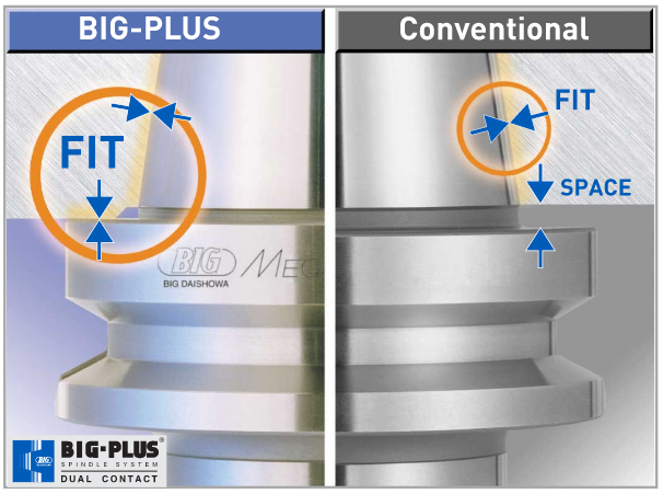
The concept of dual-contact technology has been around for years, existing in many different forms but always with the same goal of capitalizing on this untapped potential of rigidity. For those who don’t know, dual contact refers to the shank contacting the spindle taper and the spindle face simultaneously.
Oftentimes, the solution involved ex post facto alterations to the spindle or tool holder, such as using ground spacers or shims to close the gap, for example. In other words, there was no standard solution, and if you wanted dual contact, you would have to be prepared to spend time and money either buying modified tool holders or modifying them yourself to adapt them to your spindle.
BIG-PLUS emerged as a solution to this issue. Essentially, both the spindle and tool holder were ground to precise specifications so that they closed the gap between spindle face and flange in unison (while depending on very small elastic deformation in the spindle). What this meant is that operators were able to confidently switch BIG-PLUS tooling in and out of a BIG-PLUS spindle and achieve guaranteed dual contact.
Not only that, but standard tooling could still be used in a BIG-PLUS spindle if necessary, and vice versa.
Though not technically an international standard, it’s been adopted by many machine tool builders because of the clear performance improvements and simplicity. In fact, BIG-PLUS spindles come standard on more machines than you would think. We often come across operators that have machines with BIG-PLUS spindles and don’t even realize it.
It’s not too much of a leap to conclude that a larger effective diameter will give you more rigidity. That being said, you may still be asking yourself: does such a seemingly small increase in diameter really make a difference? To understand the effect of BIG-PLUS, you must understand the physics behind it.
Imagine a simple scenario in which a tool holder is represented by a cylindrical bar that is fixed at one end and free-floating at the other. In other words, a cantilever beam. If you think about it, this is essentially what a tool holder becomes once it’s secure in the spindle. Now, let’s introduce a radial force F that acts downward at the suspended end of the bar, which represents a cutting force you would encounter when milling or boring, for example. The bar, as you might expect, will want to bend downward. It’s similar to how a diving board bends when someone stands at the end, though less exaggerated.
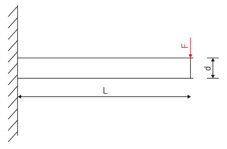
| (this depends on the bar material). The greater the value of k, the stiffer (or more rigid) our bar will be. |  |
Something interesting to note is that d is raised to the 4th power, while L is only raised to the 3rd power. Diameter affects rigidity an entire order of magnitude more than the length does. This is where the power of BIG-PLUS comes from and is why a small increase in diameter can have such a powerful effect on performance.
If you were to plug these values into the above equation for comparison, you would find that the BIG-PLUS holder results in a k value that is around 4 times greater than the standard bar. Based on this comparison, you could say that a BIG-PLUS holder is 4 times as rigid as an identical standard CAT40 holder, because it is 4 times as resistant to deflection.
Think of the tool life and surface finish improvements you would see with a tool that is 4 times more rigid, not to mention the reduction in fretting and potential for reduced cycle time. You would get similar results if you were to make the same comparison for CAT50, BT40, BT30, etc.
You’re probably wondering, at what length would a comparable standard CAT40 holder have an equal stiffness? If we take our stiffness expression and set it equal to itself (one side representing BIG-PLUS, the other non BIG-PLUS), we can plug in this BIG-PLUS holder length and our known diameters to find our unknown non-BIG PLUS length:
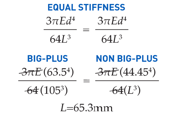
If this is true, we can say that implementing BIG-PLUS is equivalent to a 40% reduction in length in terms of rigidity. Theoretically, a BIG-PLUS tool holder will behave like a standard tool holder that is nearly half of its length!
Obviously, we’ve used simple and idealized cases here to represent the complicated and dynamic world of metal cutting. Tool holders, of course, don’t have uniform body diameters or materials and the cutting forces usually aren’t acting in one direction in a constant and predictable way. If our holder necks up and down to different body diameters along its length, which is realistically what happens, each of these sections would be its own microcosm of “beam” that would influence the overall behavior (at that point, finite element analysis on a computer becomes the only practical way to predict behavior).
So, will the advantage of BIG-PLUS really be as dramatic as our hand-calculated classical beam theory suggests? Probably not, but it depends on the tool holder/tool. Most cases will follow our simple model quite closely in practice; others not so much. If nothing else, we’ve demonstrated how dramatically the flange contact of BIG-PLUS can influence rigidity, at least in a purely mathematical sense.
As if you needed any more reasons to be on the BIG-PLUS bandwagon besides increased rigidity, you will also eliminate Z-axis movement at high speeds, improve ATC repeatability and decrease fretting. This means that you will take heavier cuts, scrap less parts, and increase tool and spindle life.
BIG-PLUS isn’t a new idea by any means, but with a proven track record of tackling tough jobs, it’s hard to imagine working in a modern machine shop and not taking advantage of what it has to offer.
If you’re still not convinced, we can also compare the rigidity in this way: Let’s say there is a Ø63.5 mm BIG-PLUS CAT40 bar of some arbitrary length. One of our more common gage lengths is 105 mm, or just over 4 inches, so let’s use it as an example.
You’re probably wondering, at what length would a comparable standard CAT40 holder have an equal stiffness? If we take our stiffness expression and set it equal to itself (one side representing BIG-PLUS, the other non BIG-PLUS), we can plug in this BIG-PLUS holder length and our known diameters to find our unknown non-BIG PLUS length:

(520) 548-7328
[email protected]
Kip Hanson is a contributing editor for Cutting Tool Engineering magazine. Originally Published: September 12, 2017 - 3:00pm
With the development of automatic toolchangers in the late 1960s, machine tool builders in Japan modified the patented design and invented the BT standard. In the 1970s, tractor manufacturer Caterpillar Inc., Peoria, Ill., changed things again with a flange design now known as CAT, or V-flange.
“Sticking” Together
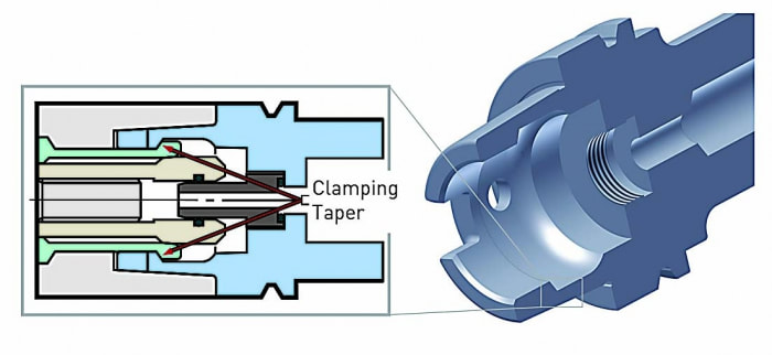
Chief among them is the tendency for the mating spindle and toolholder tapers to stick together. This is caused by the expansion of the spindle housing at high speeds, which allows the toolholder to be pulled upward into the spindle taper, jamming it in place.
One way to eliminate this problem is by extending the toolholder flange upward, thus creating a hard stop against the spindle face and preventing further Z-axis movement.
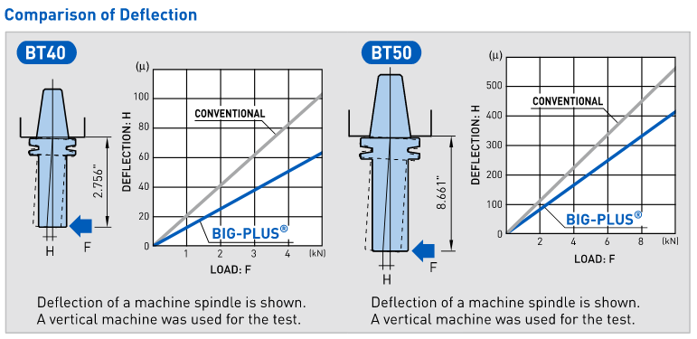
He said it’s also more rigid, with tests showing that the deflection on a CV40 BIG-PLUS toolholder measured at 70mm (2.755") from the spindle face is only 60µm (0.002") when subjected to 500kg (1,102 lbs.) of radial force, roughly half that of a traditional V-flange toolholder.
| For people who think they can’t take advantage of this technology because they don’t plan to buy a new machine, they might want to check with their distributor, as their machine may already be equipped for BIG-PLUS. | 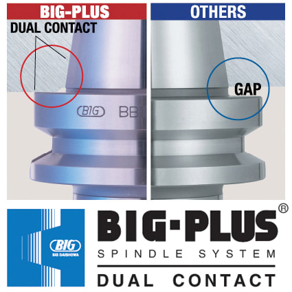 |
Revving Up
BIG-PLUS, like any dual-contact toolholder, requires particular attention to cleanliness, as chips caught between the spindle face and the toolholder can cause serious problems.
He also recommends staying below 30,000 rpm when using 40-taper holders, noting that higher speeds are better handled by HSK spindles and holders.
Keep It Clean
These requirements were impossible to meet when steep taper was first developed, Popoli said, resulting in looser standards overall for CAT and BT spindles than the ones applied to HSK spindles and toolholders. Because of this, purchasing an HSK or equivalent toolholder automatically makes one “part of the club” when it comes to balance, accuracy, repeatability and tool life.
Always stay below 20,000 rpm with 40-taper holders, and reach no more than 30,000 rpm with 30-taper ones. Use balanced holders and high-quality retention knobs that have been properly torqued—otherwise distortion at the small end of the taper may occur. And whatever the taper type, keep the spindle and toolholder clean at all times.
Bob Freitag agreed. The manager of application engineering at Minneapolis-based metalworking products and services provider Productivity Inc. said the lines are evenly split between traditional 40- and 50-taper CAT or BT tooling (much of which is BIG-PLUS) and HSK.
“It really depends on the application,” Freitag said. “Most of our die and mold machines in the 20,000- to 30,000-rpm range will have an HSK63A or HSK63F. When you get up around 45,000 rpm, you’re probably looking at an HSK32. But in horizontal machining centers and lower-rpm, high-torque verticals, you’ll see mostly steep tapers, as this is generally preferred for deep depths of cut and lower feed rates, where you’re removing a lot of material at once.”
For shops that want to make the leap to an HSK machine but are leery of investing in new toolholders, Freitag advised:
“Anytime you buy a new machine, you should buy new toolholders to go with it. If not, the imperfections of the old toolholders will soon transfer themselves to the spindle on the new machine.”
Technical Support Blog
We set up this special blog for the most commonly asked questions and machinist data tables for your easy reference.
If you've got a question that's not answered here, then just send us a quick note via email or reach one of us on our CONTACTS page here on the website.
Authorship
Our technical section is written by several different people. Sometimes, it's from our team here at Next Generation Tooling & at other times it's by one of the innovative manufacturer's we represent in California and Nevada.
Archives
July 2024
June 2024
May 2024
April 2024
March 2024
February 2024
January 2024
December 2023
November 2023
October 2023
September 2023
August 2023
July 2023
June 2023
May 2023
April 2023
March 2023
February 2023
January 2023
December 2022
November 2022
October 2022
September 2022
August 2022
July 2022
June 2022
May 2022
April 2022
March 2022
February 2022
December 2021
November 2021
October 2021
September 2021
August 2021
July 2021
June 2021
May 2021
April 2021
March 2021
February 2021
January 2021
December 2020
November 2020
October 2020
September 2020
August 2020
July 2020
June 2020
May 2020
March 2020
February 2020
January 2020
September 2019
August 2019
July 2019
June 2019
May 2019
March 2019
January 2019
September 2018
June 2018
April 2018
February 2018
December 2017
November 2017
October 2017
August 2017
June 2017
April 2017
March 2017
February 2017
January 2017
December 2016
November 2016
October 2016
August 2016
March 2016
February 2016
January 2016
November 2015
August 2015
July 2015
May 2015
April 2015
March 2015
November 2014
August 2014
July 2014
December 2013
November 2013
September 2013
July 2013
March 2013
December 2012
March 2012
November 2011
May 2011
March 2011
January 2011
December 2010
November 2010
October 2010
Categories
All
5th Axis
Aerospace
Allied Machine
Aluminum Oxide
Angle Head
AT3
Balance
Bellmouthed Hole
Big Daishowa
Big EWA Automatic Boring
Big Kaiser
BIG Plus
Blue Photon
Bone Screws
Boring Tool
Carbide
Carmex Precision
CBN
Centerline Deviation
Ceramic Black
Ceramic End Mill
Ceramic Inserts
Ceramic Oxide
Ceramic Whiskered
Ceramic White
Chamfer
Champion Tool Storage
Chip Breaking
Circular Saw
Class Of Fit
CNC Lathe Tooling
Collet
Collet Chuck
Collet ER
Collet TG
Composites
Covid-19
Deep Hole Boring
Deep Hole Drilling
Drilling
Dual Contact
Dyna Contact Gage
Dyna Force Tool
Dyna Test Bar
EMO
End Mill
Exotap
Facemill
Fixturing
Fretting
Gaylee Saw
Hard Turning
Heimatec
Helical Interpolation
Hohl Shaft Kegel
How Its Made
HSK A
HSK-A
HSK E
HSK-E
HSK F
HSK-F
HXL Tap
Hy Pro Tap
Hy-Pro Tap
IMTS
Jergens
Jergens OK-Vise
Kurt
Lang
Live Tooling
MA Ford
Maintenance Cart
Mapal
Martindale Saw
Material: Aluminum
Material: CFRP
Material: D2
Material: Hastelloy
Material: Inconel
Material: Peek
Material: Stone
Material Titanium
Material: VC 10
Material: VC-10
Metric Course Thread
Metric Fine Thread
Metric Thread Chart
Microconic
Micromachining
ModLoc
Modular
Mogul Bars
MPower
NextGen Tooling
No Go Too Loose
NTK
NTK HX5
On Site Training
OptiMill-SPM
OSG Tap & Die
Oversized Thread
Parlec
PCD
PCT Firm Hold
Platinum Tooling
Projection Length
Pull Studs
Reamer
Retention Knob
Rotary Toolholders
Rotary Toolholders BT
Rotary Toolholders CAT
Rotary Toolholders HSK
Rotary Toolholders Hydraulic
Rotary Toolholders Shrink
Rough Thread
Runout
Runout Axial
Runout Radial
Safe-Flex
Saw Selection
Short Tap Life
Sialons
Silicon Nitride
Smart Damper
Speed Increaser
SpeedLoc
Speroni STP Essntia
Spindle Mouth Wear
Surface Roughness Ra
Surface Roughness RMS
Swiss
Swiss Machining
Taper Wear
Tapping Feed
Tapping; Form
Tapping IPM
Tapping: Roll
Tapping RPM
Tapping Speed
Tap Tolerance
Technical Training
Technicrafts
Techniks USA
Thread Milling
Thread Whirling
T.I.R.
Tolerance
Toolchanger Alignment
Toolholder Taper
Tool Presetter
Torn Thread
Troubleshooting
UNC Thread Size
Undersized Thread
UNF Thread Size
Unilock
Vises
Washdown Tool
Workholding
 RSS Feed

About
|
© 2024 Next Generation Tooling, LLC.
All Rights Reserved Created by Rapid Production Marketing
|
