|
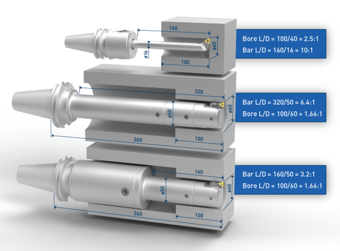
The L:D ratio of a tool assembly is calculated by using the length of the bar (or body) of a tool assembly and the diameter of the tool, not the workpiece bore diameter and depth.
To expand on this concept, we see in the first configuration below the Ø16mm bar is sticking out 160mm which is a 10:1 although the bore is only a 2.5:1. In some applications this extra reach is needed to get around a fixture or a feature of the part. However, in those cases where it is not needed, decreasing the overhang by 55mm means the new L:D of 105:16 is 6.5:1. This alone would represent approximately 10x increase in cutting speed by increasing from 20mm/min vs. 200mm/min. The use of modular reductions has also been found to be a good strategy to improve tool performance. Comparing the lower two assemblies below, the middle assembly uses the same connection size for the length of the tool, ignoring the larger access diameter, and results in a 6.4:1 ratio. When a shank with a larger connection size is used along with a modular reduction, the ratio is halved, and provides a 350% productivity improvement (14mm/min to 50mm/min). In all cases, reducing the L:D ratio provides an improvement in speed which then provides longer tool life, better surface finish and size control of the bore.
0 Comments
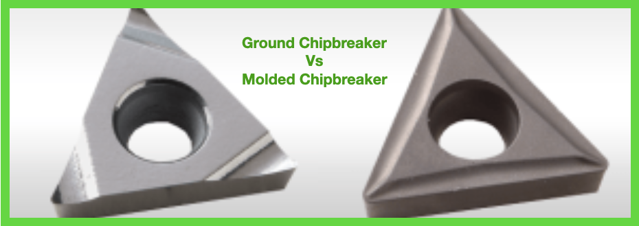
A common question asked for boring operations is when would I use a ground chip-breaker vs. a molded chip-breaker? A ground chip-breaker is recommended for chip control issues. The high-positive rake angle will help to make shorter chips, and the chip groove orientation forces the chips forward to more easily evacuate them from the bore, especially when used with high-pressure coolant through the tool. Ground chip-breaker inserts also provide lower cutting forces, so they are better suited for deep-boring or long-reach applications, and other situations where part or tool stability may not be optimal. Ground chip-breakers are also recommended for tight-tolerance applications where stock allowance is typically light for the final size pass. A molded chip breaker is recommended for stable applications in short-chipping materials. Because these situations don’t require a super-sharp edge for cutting the material, these inserts hold their edge longer for better tool life, and in most cases are less expensive. A Primer on Types of Chips
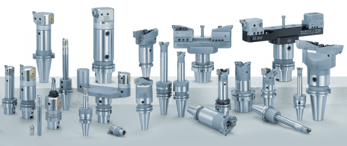
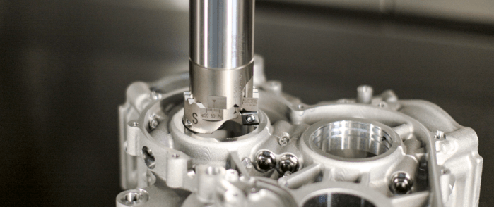
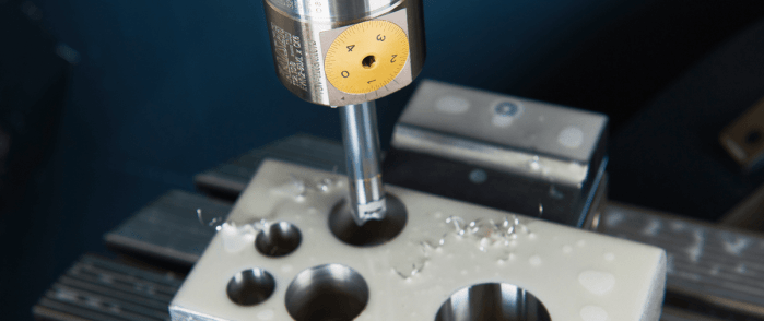
Put simply, the manufacturing process of boring is enlarging a hole in a piece of metal. There are quite a few different pieces of machinery or approaches that can be used to make holes from lathes and mills to line boring or interpolation. We wanted to do a quick break down of the different kinds of boring tools available to bore holes and/or secondary boring operations. Boring BarsBoring deep holes can involve extreme length-to-diameter ratios, or overhang, when it comes to tooling assemblies. Since it can be difficult to maintain accuracy and stability in these scenarios, we need boring bars to extend tooling assemblies and while maintaining the rigidity to make perfect circles with on-spec finishes. Solid boring bars Typically made of carbide for finishing or heavy metal for roughing, solid boring bars have dense structures that make for a more stable cut as axial force is applied. Damping bars When cutting speeds are compromised, or surface finishes show chatter in a long-reach boring operation, damping bars are an option. They have integrated damping systems. Our version, the Smart Damper, works as both a counter damper and friction damper so that chatter is essentially absorbed. Boring HeadsBoring heads are specifically designed to enlarge an existing hole. They hold cutters in position so they can rotate and gradually remove material until the hole is at the desired diameter. Rough boring heads Once a bore is started with a drill or by another method, rough boring heads are the choice for removing larger amounts of material. They are built more rigid, to handle the increased depths of cut, torque and axial forces needed to efficiently and consistently make the passes to remove materials. Fine boring heads Fine boring heads are best used for more delicate and precise removal of material that finishes the work the rough boring head started. They are often balanced for high-speed cutting since that’s the best approach for reaching exact specifications. Twin cutter boring heads Most boring heads feature one cutter that cuts as its feed diameter is adjusted by the machine. There are twin cutter boring heads that can speed up cutting and add versatility. For example, the Series 319 and other BIG KAISER twin cutter boring heads include two cutters that can perform balanced or stepped cutting without additional accessories or adjustments by switching the mounting locations of the insert holders that have varied heights. Digital boring heads Traditionally, adjusting boring heads has been painstaking and time-consuming, especially when it’s done in the machine. It’s easy to make mistakes when maneuvering to read the diameter dial and adjusting it to the right diameter. Digital boring heads have a LED that makes precise adjustments much easier. Starter DrillsSince cutters are on diameter of boring heads and not their face, they are not able to initiate a hole on a flat surface or raw material. Especially in smaller bores, fluted drills called starter drills can be used to get the hole started before rough boring.
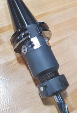
Specialty boring heads Back boring and face grooving heads, as well as chamfering insert holders, are available for some of the most common secondary operations, after a hole is bored. We produce specific heads with cutters at the appropriate angles so each of these operations can be done without manually moving the part, changing the tool or adjusting the cutter angle. Modular boring tools Since limiting length-to-diameter ratios is so crucial to boring success, it’s extremely valuable to be able to make your tooling assembly as short as possible. Our modular components are based on a cylindrical connection with radial locking screw that allows for the ideal combination of different kinds of shanks, reductions and extensions, bars, ER collet adapters and coolant inducers. Looking for some help finding the right boring equipment for your next job or new machine? Our engineers are here to help. Get in touch with us here. It’s time for machine tool builders and machining companies to shelf the long-standing ISO 1940-1 standard in favor of ISO 16084:2017. Not only is balancing tools rarely necessary, it can also be risky. A lot of conflicting information has circulated over the years about balancing tools. As an author of the new standard for calculating permissible static and dynamic residual unbalances of rotating single tools and tool systems – ISO 16084:2017 – allow me to clear some things up and, hopefully, make life a little easier for you.
Since its institution in 1940, the G2.5 balance specification has been widely accepted across the industry; i.e., “it’s how things have always been done.” However, machines were much slower 80 years ago. Back then, the most advanced machines would have spun larger, heavier tools at a maximum speed of about 4,000 RPM. If you applied the math from those days to today, you’d get unachievable values. For example, the tolerances defined by G2.5 for tools with a mass of less than 1 pound rated for 40,000 RPM calculates to 0.2 gram millimeters (gm.mm.) of permissible unbalance and eccentricity of 0.6 micron. This isn’t within the repeatable range for any balance machine on the market. Similarly, application-specific assemblies, for operations like back boring and small, lightweight, high-speed toolholders, can’t be accurately balanced for G2.5. Machine tool builders rely on an outdated number, too, often basing spindle warranty coverage on using balanced tools at very specific close tolerances. While it’s true that poorly balanced tools run at high speeds wear a spindle faster, decently balanced tools performing common operations won’t wear spindles or tools drastically and deliver the results you’re looking for. While it’s true that poorly balanced tools run at high speeds wear a spindle faster, decently balanced tools performing common operations won’t wear spindles or tools drastically and deliver the results you’re looking for. A Little Lesson About ForcesThis all begs the question: When do you need to take the time to balance holders? I would argue that tools require balancing only if they’re notably asymmetrical or being used for high-speed fine finishing. Here’s a rule I’ve long followed: If cutting forces exceed centrifugal forces due to unbalance, high-precision balancing isn’t needed because the force required to balance the tool will most likely be less than cutting forces.
At that point, aggressive cutting – not unbalance – is going to damage the spindle. Unbalanced tools are also blamed for issues that turn out to be misunderstandings about a machine’s spindle. I’ve visited shops with new high-speed spindles that had trouble running micro tools over 15,000 RPM. They rebalanced all the tools on the advice of their machine tool supplier, but to no avail. It turned out the machine was tuned for higher torque and higher cutting forces. Before going to the effort of balancing toolholders, work with your machine builder to understand where a spindle is tuned. Not only is balancing tools rarely necessary, it can also be risky. Our inherently asymmetrical fine-boring heads are a good example. Because we balance them at the center, a neutral position of the work range, you lose that balance if you adjust out or in. To adjust, you’d typically add weight to the light side, which can be a problem for chip evacuation and an obstructor. Or you can remove weight from the heavy side, but that means you have to put some big cuts on the same axis of the insert and insert holder, ultimately weakening the tool. In longer tool assemblies, common corrections made for static unbalance can also cause issues. It happens when a toolholder is corrected for static unbalance in the wrong plane; i.e., adding or removing weight somewhere on the assembly that’s not 180 degrees across from the area where there’s a surplus or deficit. Once the tool is spun at full speed, those weights pull in opposite directions and create a couple unbalance that often worsens the situation. A Cautionary TaleIf you do go down the balancing road, you’d better know where you can modify tools, what’s inside, how deep you can go, and at what angles. Whether you’re adding or removing material on a holder, I highly recommend consulting the tool manufacturer for guidance first. As a cautionary tale, consider a customer who was attempting to balance a batch of our coolant-fed holders. Based on the balancing machine, the operator drilled ¼-inch holes at the prescribed angle into the body of the holders. Not realizing what was inside, he drilled into cross holes connecting coolant flow and ruined several holders. Tooling manufacturers are doing their part to avert disasters like this. For most, simple tools like collet chucks or hydraulic chucks are fairly easy to balance during manufacturing. We account for any asymmetrical features while machining and grinding holders and pilot each moving part, ensuring they’ll locate concentrically during assembly. These measures ensure the residual unbalance of the assemblies is very, very low and eliminate the need for balancing.
Decades of the same standards have conditioned us to think a certain way about balancing tools. While it seems logical that every tool must be balanced, it’s just not the case: Many issues attributed to unbalance aren’t caused by unbalance, and the risks of balancing every single tool often aren’t worth the reward.
Save your balancing time and resources for high-speed fine finishing. If you do have work where balance is crucial, consider how the tools you buy are balanced and piloted out of the box and/or consult your partners before making any modifications. We are very excited to announce that we are now able to offer on-site technical training to YOUR machinists at YOUR location! This is offered at no charge to customers who use any of the manufacturer's whom we represent in California and Nevada. However, just because you don't purchase things from us, don't feel left out! We also offer on-site topic specter training on any of the following topics for $150/hour. Each presentation lasts about 2 hours. The presentations last approximately 45-60 minutes with the remaining time for Q&A and discussion about unique applications in your facility.  Training Classes Available: Machining 101
Advanced Part Manufacturing:
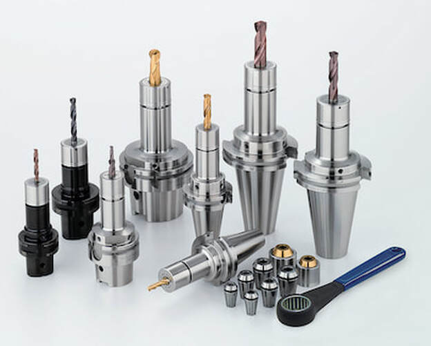
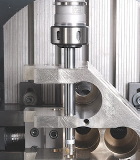
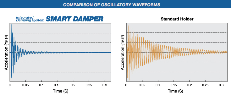
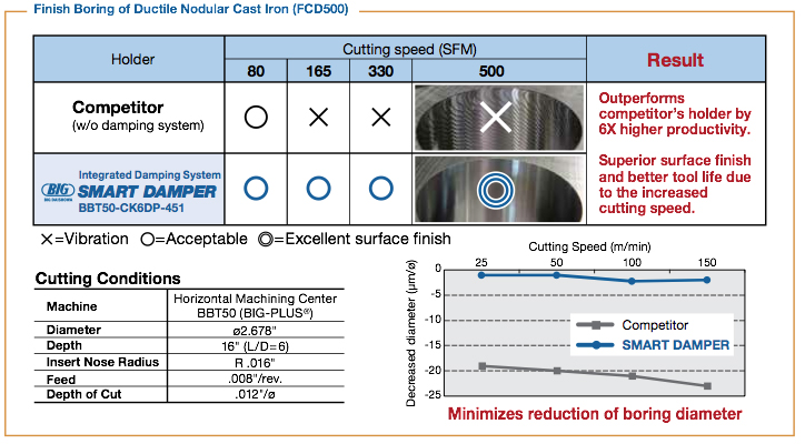
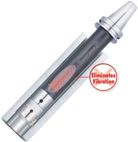
The EWD Smart Damper damps vibrations and reduces chatter in deep-hole finish boring and extended-reach face milling applications – thus achieving better surface finishes and improved metal removal rates. For precision machining of deep bores, it has previously been necessary to choose low cutting data in order to prevent vibrations, which massively increases processing time. The EWD Smart Damper overcomes this problem, and enables high cutting parameters to be used. This means that extremely short turnaround times can be achieved, which improves productivity by up to a factor of ten. Features
Smart Damper products are designed for deep-hole boring with BIG KAISER’s CKB modular boring system, and also for extended reach milling with both inch- and metric-pilot shell mills and face mills. The original rollout of the Smart Damper for finish boring included an integral BCV50, BBT50 and HSK-A100 tool holder with a CKB modular connection at the business end. A BCV50 integral 1” shell mill holder was also available. The next phase of the Smart Damper accounted for more flexibility towards assembling a more custom tool assembly. A modular CKB Smart Damper Extension allowed customers to mount it to any combination of standard CKB shanks, extensions and reductions to create the exact tool configuration for their job. At the same time, a modular thread-on face mill damper head extension was also developed to be used with matching basic holder with different interfaces and gauge lengths. This new design for boring shortens the distance from the damping mechanism to the cutting edge, which is the source of vibration. This produces higher damping effects to the tool assembly to minimize the chatter or vibration – thus achieving better surface finishes and improved metal removal rates.
For more information on Smart Damper Models:
Visitors at the 2015 EMO tradeshow in Milan, Italy, were the first in the world to see our newest solution in the Smart Damper family – EWN and EWD BIG KAISER boring heads with an integral damping system.
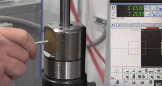
If you're just learning about it now you should get in touch with us so we can show you lots of new application solutions! Our most widely used finish boring system, BIG KAISER Series 112, features a high precision boring head with a center-mount boring bar or boring bar/insert holder combo with a predefined fixed offset designed to bore one specific size. Although the BIG KAISER system provides a multitude of standard components to create the ideal combination of boring bar and insert holder – you may not always have the ideal combination at your disposal. Don’t fret – that is the beauty of the system. The total boring range of your assembly is reached through radial adjustment of the bar. However, when doing so, there is still always the consideration of balance while assembling the tool. As logic would tell you, the farther away from the boring head’s centerline you offset the boring bar, the greater the unbalance. This affects not only the performance of the tool, but more importantly, the results. And this is especially true for deep hole boring. To get the greatest productivity and flexibility from the BIG KAISER 112 boring system, we recommend replacing the fixed bar & insert holder with a radial adjustment bar & insert holder which keeps the bar at centerline at all times. This allows for different boring ranges to be reached, all while keeping the tool as balanced as possible. In this video, Matt Tegelman, Applications Manager and BIG KAISER Product Manager, walks you through the process of adjusting the fixed boring bars and inserts holders. And if balance is a concern, utilizing the radial adjustable option, Matt demonstrates how to properly center the boring bar on both a tool presetter and in a machine spindle, and finally, how to fine-adjust to the desired diameter. Watch for more of these brief instructional reference videos here on Cut to the Chase blog in the near future.
Tags: balance, boring tool, deep hole boring, How-To, KAISER, Matt Tegelman, tool presetter |
Technical Support BlogAt Next Generation Tool we often run into many of the same technical questions from different customers. This section should answer many of your most common questions.
We set up this special blog for the most commonly asked questions and machinist data tables for your easy reference. If you've got a question that's not answered here, then just send us a quick note via email or reach one of us on our CONTACTS page here on the website. AuthorshipOur technical section is written by several different people. Sometimes, it's from our team here at Next Generation Tooling & at other times it's by one of the innovative manufacturer's we represent in California and Nevada. Archives
July 2024
Categories
All
|
About
|
© 2024 Next Generation Tooling, LLC.
All Rights Reserved Created by Rapid Production Marketing
|


 RSS Feed
