 For all BIG KAISER fine boring heads type AW, EW, EWN, EWD, EWE, EWB and EWB-UP, the frequency for lubrication depends on use.
If used daily, the recommendation is to oil the boring head every two to three months. The best procedure is to range the cartridge to the maximum diameter. Using a lubrication gun, pump oil in the unit until it stops accepting oil and then range cartridge to minimum setting. Excess oil will come out around the dial face (this is normal). If oil is excessively dirty, repeat the process. Recommended oils are Mobil Vactra No. 2, BP Energol HLP-D32, Kluber Isoflex PDP 94, or a similar light machine oil.
0 Comments
A brief history of wedge operated workholding clamps by Olavi Meriläinen, Jergens guest blog  In the late 1970’s, Finnish inventor and entrepreneur Mr. Olli Kytölä developed a new clamping method for workholding. The simplicity of the idea is mind-blowing even today: instead of moving large machine vise jaws against each other, a small wedge-operated jaw is pressing the workpiece against fixed stoppers. The clamp has two jaws, so possibility to clamp one or two workpieces with one clamp is built-in. The clamping itself is very simple. When we are tightening the clamp, the wedge in the middle pushes the jaws sideways, pressing the workpiece against a fixed stopper. During last 40 years, this wedge operated workholding clamp has become famous with the name OK-VISE Low-Profile Clamp. The core application has always been in CNC milling, an in early days do-it-yourself people used to build their own workholding fixtures using OK-VISE clamps and milling the remaining parts of the milling fixture themselves.
These modules locate the workpiece, and clamps are used in most cases to clamp the workpiece against stoppers. The clamping itself is very simple. When we are tightening the clamp, the wedge in the middle pushes the jaws sideways, pressing the workpiece against a fixed stopper. In addition to dedicated workholding, the low-profile clamp is often used in modular workholding systems, such as Multi-Rail RM. This approach, involving standardized modules for fixture designers and fixture builders, speeds up fixture sourcing radically, especially if a modular base rail is in use. Best-case scenario is that no machining at all is needed to build a new fixture
Different clamp modelsWhen we are talking about clamping the workpiece securely and safely for machining, it is important to look at various clamp models and their strengths. The features of the machining process and the workpiece typically determine the requirements for the clamp. In most fixtures, so called force-closure is being used. This means that typically 3 sides of the workpiece have free access to milling tool, and holding force opposing the machining forces is created by friction. When dealing with high forces during machining in force-closure fixtures more friction is needed between the jaw and the workpiece. This can be achieved by selecting a larger clamp, for bigger forces, or a model with enhanced grip for better friction compared to a smooth-jaw clamp. Luckily, you can find a range of clamp options from us to securely attach even the most challenging workpieces. For better friction
It has to be noticed that the marks that these jaws leave to the workpiece are almost invisible.
For complicated shapesSometimes the workpiece has a complex shape, which we need to consider when selecting the right clamp. In these cases, the clamp can have an adjustable jaw, or the jaw itself can be machined to match the shape of the workpiece.
Direction of the jaw movementIn mostly used the jaw slides along the fixture base. These are called hold-down models, because the wedge design holds the jaw down and prevents the jaw from lifting up while clamping.
Friction in low-profile clamp fixtures..more typical application is force-closure, where the friction between the workholding clamp and stopper jaws create a holding force that prevents the workpieces from moving. One way to build a workholding fixture is form-closure, where the geometry of the layout prevents the workpieces from moving. Another and more typical application is force-closure, where the friction between the workholding clamp and stopper jaws create a holding force that prevents the workpieces from moving. In most typical application there are 2 workholding clamps and 2 stoppers, each with the same force clamping the workpiece. When this force is multiplied by friction coefficiency µ, then we can calculate the holding force, in the abovementioned example.  OK-Vise Friction in low-profile clamp fixtures diagram H = 4 µ F where F is the clamping force, and friction coefficient varies. Example values when workpiece from steel is in use. µ = 0,15 smooth jaws µ = 0,28 tungsten carbide coated jaws µ = 0,8 serrated jaws What we have learnedAll in all, using a wedge operated clamp is one of the easiest and best ways to build workholding fixtures. Its operation allows you to use it for clamping multiple workpieces simultaneously or when you need a high clamping force in limited space. For more details about our low-profile clamp, we have gathered product information in our instructions.
Stay tuned for more updates from OK-VISE as the company continues to innovate and deliver cutting-edge solutions to its customers. Here are some basic rules of thumb on end mill selection 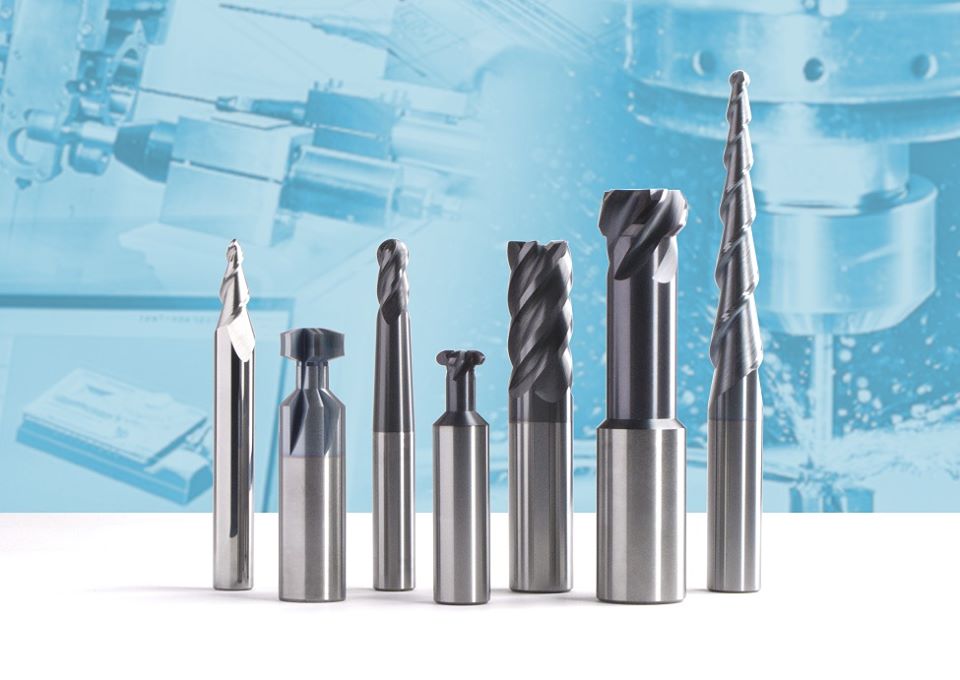 Navigating the vast array of end mills available in the market can be a daunting task, especially when precision is paramount. To aid in this process, we've outlined a step-by-step guide that addresses crucial considerations for selecting the optimal end mill for your machining needs.
Step 1 – Material Identification: Identify the exact material, its condition (billet, forging, etc.), and hardness (HRC). This information directs you to the Non-Ferrous or Ferrous section of our catalog. Step 2 – Operation Type: Determine whether you'll be roughing, finishing, or both. This guides the choice of the number of flutes and the need for chip breakers. Step 3 – Programming Style: Choose between traditional programming, high efficiency programming (HEM), or a combination. This decision influences the number of flutes (Step 8). Step 4 – ADOC (Axial Depth of Cut): Determine the maximum axial depth of cut the tool will experience in the part. This information helps decide the length of cut (LOC) to deploy. Step 5 – Reach Consideration: Evaluate obstacles to clear and depths to reach. If necessary, consider a reduced necked tool to maintain length of cut while reaching deeper positions. Step 6 – Tool Diameter Selection: Consider the machine taper, cut depth, reach, and part geometry. Keeping the tool diameter under 3/4" for 40-taper machines and adapting the diameter to programming style, cut depth, and reach requirements. Keep in mind what programming style (Step 3) you’re using as HEM can employ smaller diameters than you may be used to. Decide on your cut depth (Step 4). For traditional programming keep it <2xDia., for HEM keep it below 4xDia. Decide on your total reach depth (Step 5). If needing to machine 4xDia. look at a necked tool to maintain strength and minimize deflection. Step 7 – Corner Radius: Determine if your part requires a corner radius. Running a corner radius on an end mill can extend its life and is especially beneficial for pre-finishing. Step 8 – Flute Count: Consider the material and programming type to determine the ideal flute count. Non-Ferrous machining typically requires 2-3 flutes for traditional programming and 3-5 for HEM, while Ferrous machining may need 4-5 for traditional programming and 5-7 for HEM. Step 9 – Tool Holder Selection: Always opt for the most rigid and accurate tool holder with minimal runout. Keep the Total Indicator Runout (TIR) below 0.0005 at the tip of the tool for optimum tool life and success. Consider the use of a side lock holder for specific applications. Remember, our team at Next Gen Tooling is always available to assist you in selecting the correct product. By following these guidelines, you'll navigate the selection process with confidence, ensuring precision and efficiency in your machining operations. compiled & edited by Bernard Martin 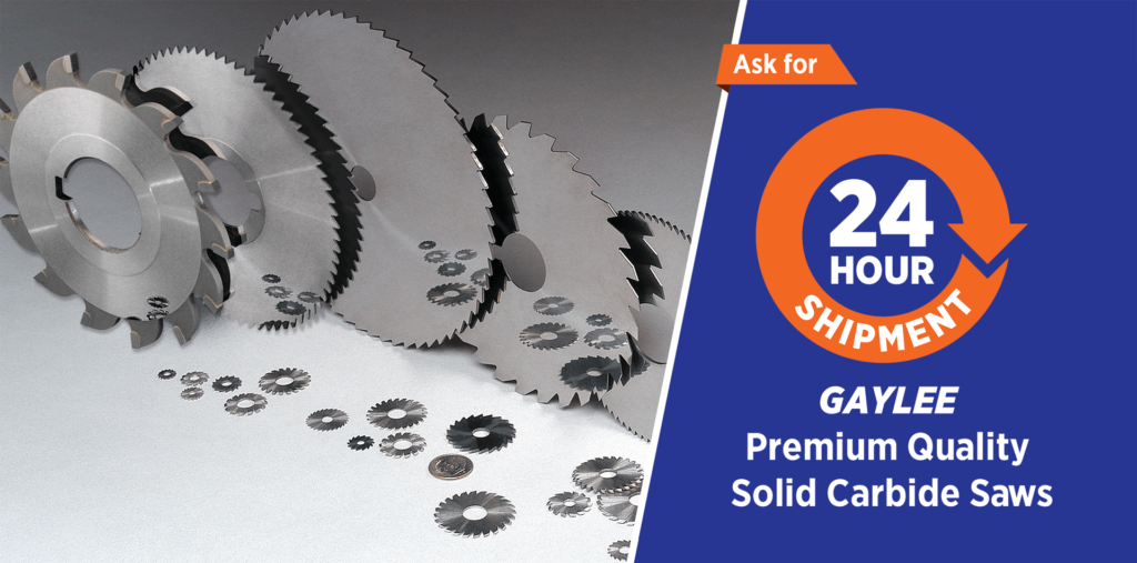 Carbide and HSS circular saws are essential tools in the metalcutting industry, however, breakage issues arise that impact performance and efficiency. In this article, we'll look into the common causes of carbide circular saw breakage and provide insights into preventive measures to enhance saw longevity. Key Factors Influencing BreakageSaw Thickness and Keyways:
Monitoring HSS Saw Colors Preventive MeasuresWasher Size and Equal Diameter
Understanding the factors contributing to carbide circular saw breakage is crucial for efficient and safe operation. By addressing key issues such as washer mounting, cleanliness, and proper tightening, operators can significantly enhance the lifespan of their saws. Regular inspections, maintenance, and adherence to recommended operating practices are vital to preventing breakage and ensuring optimal performance in various metalcutting applications.
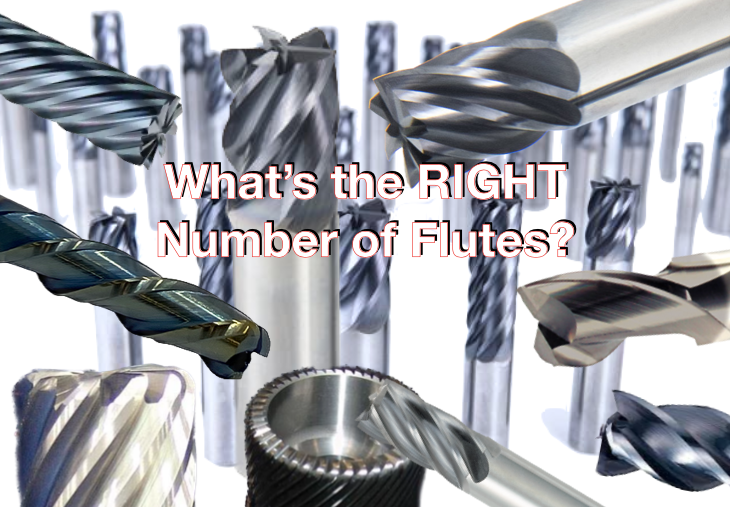 The number of flutes on a carbide end mill significantly influences its performance across various machining applications. How many flutes do you need? The simple answer: It depends. Obviously there are a quite a number of other factors that impact an end mills performance such as helix angel, edge prep, gullet depth and radius. We can't tackle everything in this article, but hopefully this helps you get a better understanding of why there are different numbers of flutes on end mills. Below is an overview of the advantages and disadvantages associated with end mills featuring different flute counts, along with recommendations for materials based on ISO 513 categories (P, M, K, N, S, H) Single Flute End Mills
2-Flute End Mills
3-Flute End Mills
4-Flute End Mills
5-Flute End Mills
6-Flute End Mills
7-Flute End Mills
8-Flute End Mills
0-Flute End Mills
Advantages of Higher Flute Counts in |
Technical Support BlogAt Next Generation Tool we often run into many of the same technical questions from different customers. This section should answer many of your most common questions.
We set up this special blog for the most commonly asked questions and machinist data tables for your easy reference. If you've got a question that's not answered here, then just send us a quick note via email or reach one of us on our CONTACTS page here on the website. AuthorshipOur technical section is written by several different people. Sometimes, it's from our team here at Next Generation Tooling & at other times it's by one of the innovative manufacturer's we represent in California and Nevada. Archives
July 2024
Categories
All
|


 RSS Feed

About
|
© 2024 Next Generation Tooling, LLC.
All Rights Reserved Created by Rapid Production Marketing
|
