 The four critical requirements for tool holders are clamping force, concentricity, rigidity, and balance for high-spindle speeds. When these factors are dialed in just right, there’s nearly no chance of holder error and considerable cost reduction is achieved thanks to longer tool life and reduction of down-time due to tool changes. Easier said than done, our experts shared some of their best, quick-hitting advice for top tool holder performance in different situations. 1. Balance holders as a complete assembly Long-reach milling has some unique demands; when setting up this type of job, always balance tool holders as a complete assembly. While many tooling providers pre-balance their holders at the factory, it’s often inadequate, especially for long-reach applications. 2. Holder damage can go from bad to worse quickly Wear and tear on holders can be costly in the end, but there are ways to protect against it. Inspect and care for your holders. Trauma on a holder or spindle—dings, scratches, gouges, etc.—can magnify quickly. One bad holder can spread its problems like an illness. If you’re seeing disruptions like these on your holders, get them out of the rotation. 3. The rule of thumb on holder dimensions Looking for affordable ways to avoid vibration? Start by opting for a holder with a combination of the largest diameter and shortest length possible. 4. Rigidity can harm tapping operations What many don’t realize about tapping operations is that a perceived strength of collet chucks—their rigidity—can actually be detrimental. Rigidity does very little to counteract the dramatic thrust loads imposed on the tap and part, exacerbating the already difficult challenge of weathering the stop/reverse and maintaining synchronization. 5. Balancing is crucial to five-axis machining Five-axis machining introduces a whole new set of tooling challenges. While important in any type of machine, balance may be of most importance in full five-axis work. A well-balanced holder helps ensure the cutting edge of the end mill must be consistently engaged with the material in order to prevent chatter and poor surface finish quality. 6. Consider spindle speed requirements when choosing between shrink-fit and hydraulic holders If you have to choose between shrink-fit and hydraulic holders in a long-reach application, consider the spindle speed required. If a hydraulic chuck exceeds its rated RPM, fluid is pulled away from the holder’s internal gripping gland, causing loss of clamping force. But when used within its recommended operating range, a hydraulic tool holder offers superior runout and repeatability. On average, a good shrink-fit holder has about 0.0003-inch runout, while a hydraulic chuck offers 0.0001 inch or better. 7. Don’t overlook the tool’s effect on holder performance The cutting tool affects holding ability more than most machinists and engineers realize:
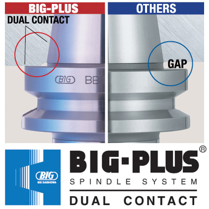
8. Not all dual-contact tooling is the same Anyone in the market for BIG-PLUS dual-contact tooling should consider this simple statement: Only a licensed supplier of BIG-PLUS has master gages that are traceable to the BIG grand master gages and have the dimensions and tolerances provided to make holders right. Everyone else is guessing and using a sample BIG-PLUS tool holder as their own master gage—a practice that any quality expert will advise against. Look for the marking: “BIG-PLUS Spindle System-License BIG DAISHOWA SEIKI.” 9. You may have a BIG-PLUS spindle and not even know it You’d be surprised how often we hear from our certified regrinders or engineers in the field about folks that didn’t realize their machine had a BIG-PLUS spindle—the message can get lost in the supply chain or during the sales process. The easiest way to know if an interface is BIG-PLUS is to place a standard tool into the spindle and see how much of a gap there is between the tool holder flange face and spindle face. Without BIG-PLUS, the standard gap should be visible, or about 0.12 in. If it is BIG-PLUS, the gap is half of this amount, or only 0.06 in. These values change depending on 30 taper, 40 taper or 50 taper sizes, but the gap is visibly less than usual. 10. Use positive offsets during holder setup It may be how it’s traditionally been done but touching off holder assemblies in each machine to establish negative tool offsets based on the zero-point surface—the vise, machine table, workpiece, etc.—is not the most efficient process. We think the choice is pretty clear: adapting machines to a single presetter so they can receive positive gage lengths is superior to using all types of machine-specific negative offsets.
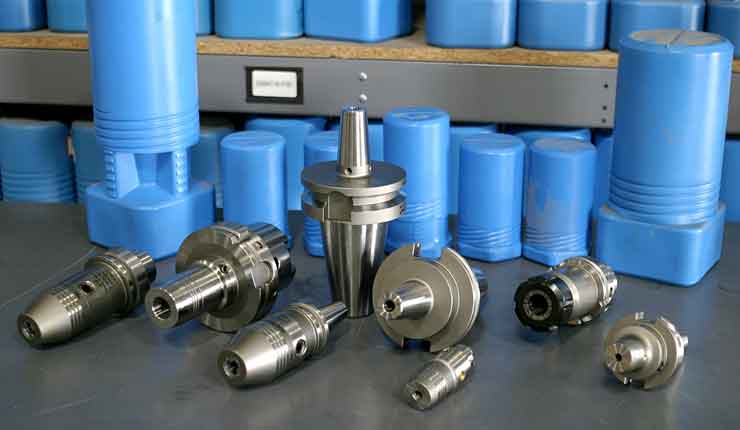
This is a change to “the way things have always been done” that can be met with some resistance, but in the grand scheme of things, it’s a relatively small and simple step that makes life much easier. It’s a relatively low-cost opportunity to introduce more standardization of holder setup to the shop floor. Holders are the bridge between the machine and the part. That’s a lot of pressure—literally and figuratively. It’s important to select, care for and use holders carefully from the day they are purchased until they’re tossed into the recycling bin. From collet chucks to coolant inducers, BIG KAISER is North America’s source for standard-bearing tool holders that guarantees high performance. Explore the full lineup.
0 Comments
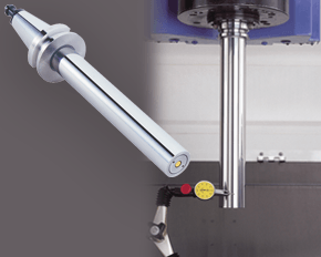
A machine’s spindle is one of the key links in the machining chain. In other words, if there are irregularities inside or at the face, they can show up on your part. It makes regular inspection and spindle maintenance critical to getting the most out of your equipment and maintain process efficiency. These three accessories, the Dyna Contact Taper Gage, the Dyna Test Bar and the Dyna Force Measurement Tool, can help you perform this maintenance easily without eating into valuable spindle time. Dyna Contact Taper Gage
Dyna Test Bar
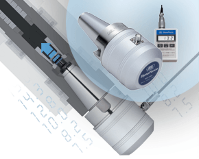
With the help of a dial indicator, you can uncover any runout while safely spinning the spindle at a very low RPM and verify the parallelism of Z-axis motion. Dyna Force Measurement Tool
The Dyna Force measurement tool provides a precise digital reading that reveals reduction in retention force in increments of 0.1kN. If you would like a demonstration for any of these tools contact us or set up an appointment for one of our Next Generation Tooling engineers to visit you!
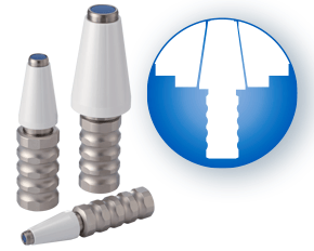
A guest blog from BIG KAISER. 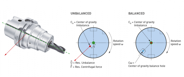 High-speed machining started getting popular in the ‘90s, especially in aerospace where they replaced fabricating processes with machining monolithic parts like wing struts from billets. Machine tools capable of spinning cutting tools at tens of thousands of RPM made it easier to produce these parts quickly. Like machines, holders adapted. The centrifugal forces they had to manage in order to keep tools cutting correctly became extreme. The toolholding systems available at that time were found not to be as effective as the shallower 1-to-10 taper ratio of the German hollow taper shank, hohl shaft kegel (HSK) in German. The HSK has since been standardized to ISO specifications (12164-1, -2). HSK is now available in several sizes and forms to fit with small to large machines. For the most part, the market has settled on the form A for general milling. It has been adopted in Japan, North America and Europe and is truly one of the only worldwide-side toolholder standards. Form E or F is for high-speed machining. The forms have different features depending on the standard they follow. In the end, to achieve efficient tool life, proper finish and productivity in high-speed work, holders need to be as rigid, compact and short as possible to keep the whole assembly stable. What to know when choosing a high-speed tool holder
When it comes to balancing holders, the quality G2.5 is widely used in the industry and is described in the ISO 1940-1 (issued in 2003) standard. However, this quality class is often over-specified and is in many cases not economically or technically feasible, especially when applied to smaller and lighter tools. Standards often applied to tools are more suited for rigid rotors and are practical in a broader use for balancing.
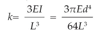
However, it cannot be applied to a complete system of spindles, tool holders and tools adequately and within technical constraints. For example, a tool to be compliant will have to be balanced to less than 1 gmm/kg at a speed of 25,000 rpm, which in turn corresponds to a mass eccentricity of less than 1 μm. This allowable tolerance is less than the interchange accuracy for even HSK, essentially negating all the costs and time for balancing the tool to such a strict tolerance. For this reason, all BIG KAISER tool holders are balanced according ISO 16084 (issued in 2017) specifically developed for rotating tool systems. ISO 16084 focuses on the interaction between spindle and tool factoring in the allowable load on the spindle bearings generated by the tool’s imbalance. This load must not exceed one percent of the dynamic load capacity of the spindle bearings. According to ISO 16084, the allowable unbalance tolerance is specified in [gmm] and is not expressed using a special quality grade [G]. In conclusion, BIG KAISER does not indicate any G-values for balancing quality, but rather the maximum rotational speeds of the individual tool holder. The BIG Kiaser MEGA holder program includes a variety of styles that can be used up to 40,000 RPM. They guarantee 100 percent concentricity and runout accuracy down to .00004" at the nose. They are built specifically to withstand speed and forces required in today’s high-throughput environment. For more information on BIG KAISER's approach to balancing tool holders, click here. To learn more about our high-performance tool holders here.  Spindles and tool holders are in a constant battle with the forces of nature, with this battle becoming more and more difficult with heavier cuts and longer projections. Chattering and deflection have always been the bane of machinists’ existence, so much so that the sight of a long and slender toolholder will immediately cause goosebumps. If you understand why a long tool holder behaves the way it does, you’ll know that there are ways to fight back against this bending. Every machinist knows that short and stubby holders are more resistant to deflection than long and slender holders. You’ve also probably heard that, if possible, you’ll want most of your cutting forces to be axial rather than radial. Not only does this fight chatter in operations like boring, but your spindle also is better equipped to handle loads in this axis. However, these options aren’t always going to be on the table, especially in unavoidable long-reach situations and many milling operations. In this constant battle with tool deflection, much time and effort has been spent designing shorter holders, stiffer tools, and clever anti-vibration geometry and materials. But oftentimes, the body diameter(s) of the holder can be overlooked as a means of increasing rigidity, especially in situations where it is all you have to work with. This is a serious shame, as you’ll soon discover. The concept of dual-contact technology has been around for years, existing in many different forms but always with the same goal of capitalizing on this untapped potential of rigidity. For those who don’t know, dual contact refers to the shank contacting the spindle taper and the spindle face simultaneously. Oftentimes, the solution involved ex post facto alterations to the spindle or tool holder, such as using ground spacers or shims to close the gap, for example. In other words, there was no standard solution, and if you wanted dual contact, you would have to be prepared to spend time and money either buying modified tool holders or modifying them yourself to adapt them to your spindle. BIG-PLUS emerged as a solution to this issue. Essentially, both the spindle and tool holder were ground to precise specifications so that they closed the gap between spindle face and flange in unison (while depending on very small elastic deformation in the spindle). What this meant is that operators were able to confidently switch BIG-PLUS tooling in and out of a BIG-PLUS spindle and achieve guaranteed dual contact. Not only that, but standard tooling could still be used in a BIG-PLUS spindle if necessary, and vice versa. Though not technically an international standard, it’s been adopted by many machine tool builders because of the clear performance improvements and simplicity. In fact, BIG-PLUS spindles come standard on more machines than you would think. We often come across operators that have machines with BIG-PLUS spindles and don’t even realize it. 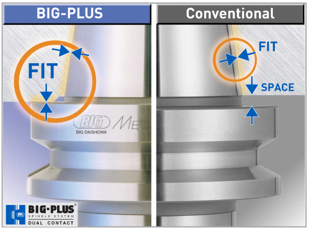 How exactly does dual contact help with tool rigidity? The torque (or moment) exerted by the cutting forces is maximized at the point where the holder and spindle meet, the base of the tool holder. With standard CAT40 tool holders, this would be the gage line diameter. When the holder contacts the spindle face via BIG-PLUS, the effective diameter would be the larger diameter of the v-flange, since this is the new anchoring point of the holder and spindle. So, you are beefing up the diameter at the point where the reactionary force is greatest. It’s not too much of a leap to conclude that a larger effective diameter will give you more rigidity. That being said, you may still be asking yourself: does such a seemingly small increase in diameter really make a difference? To understand the effect of BIG-PLUS, you must understand the physics behind it. Imagine a simple scenario in which a tool holder is represented by a cylindrical bar that is fixed at one end and free-floating at the other. In other words, a cantilever beam. If you think about it, this is essentially what a tool holder becomes once it’s secure in the spindle. Now, let’s introduce a radial force F that acts downward at the suspended end of the bar, which represents a cutting force you would encounter when milling or boring, for example. The bar, as you might expect, will want to bend downward. It’s similar to how a diving board bends when someone stands at the end, though less exaggerated. 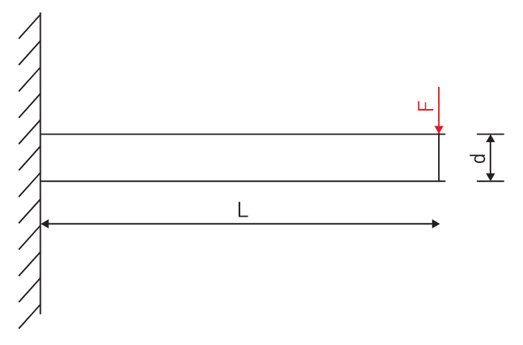 It’s possible to predict the amount of deflection (or inversely, bending stiffness) at the end of this hypothetical bar if you know its length, diameter and material. The expression below represents the stiffness k at the end of the bar where d=diameter, L=Length and E=Modulus of Elasticity
I won’t ask you to do any math here, I just want you to look at the equation. We can see that increasing d will increase the value of k, while increasing L will decrease the value of k, since it’s in the denominator of the equation. This certainly makes sense if you think about it: a short and squat bar (large d, small L) will be more rigid than a long and slender bar (small d, large L). Something interesting to note is that d is raised to the 4th power, while L is only raised to the 3rd power. Diameter affects rigidity an entire order of magnitude more than the length does. This is where the power of BIG-PLUS comes from and is why a small increase in diameter can have such a powerful effect on performance.  For a CAT40 tool holder, the gage line diameter is Ø44.45 mm and the flange diameter is Ø63.5 mm. Let’s imagine two bars of identical length and material, so L and E remain unchanged. One bar has a diameter of Ø44.45 mm (standard CAT40) and the other has Ø63.5 mm (BIG-PLUS CAT40). If you were to plug these values into the above equation for comparison, you would find that the BIG-PLUS holder results in a k value that is around 4 times greater than the standard bar. Based on this comparison, you could say that a BIG-PLUS holder is 4 times as rigid as an identical standard CAT40 holder, because it is 4 times as resistant to deflection. Think of the tool life and surface finish improvements you would see with a tool that is 4 times more rigid, not to mention the reduction in fretting and potential for reduced cycle time. You would get similar results if you were to make the same comparison for CAT50, BT40, BT30, etc. 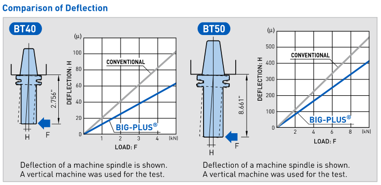 If you’re still not convinced, we can also compare the rigidity in this way: Let’s say there is a Ø63.5 mm BIG-PLUS CAT40 bar of some arbitrary length. One of our more common gage lengths is 105 mm, or just over 4 inches, so let’s use it as an example. You’re probably wondering, at what length would a comparable standard CAT40 holder have an equal stiffness? If we take our stiffness expression and set it equal to itself (one side representing BIG-PLUS, the other non BIG-PLUS), we can plug in this BIG-PLUS holder length and our known diameters to find our unknown non-BIG PLUS length: 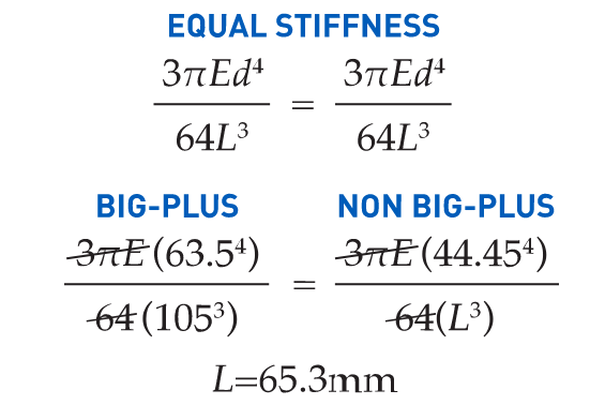 What does this mean? A BIG-PLUS holder of around 4 inches or 105 mm in length will have equal rigidity to a standard CAT40 holder of around 2.5 inches or 65 mm in length. Any experienced machinist will know quite well the difference in rigidity between a 4-inch long holder and a 2.5-inch long holder.
If this is true, we can say that implementing BIG-PLUS is equivalent to a 40% reduction in length in terms of rigidity. Theoretically, a BIG-PLUS tool holder will behave like a standard tool holder that is nearly half of its length! Obviously, we’ve used simple and idealized cases here to represent the complicated and dynamic world of metal cutting. Tool holders, of course, don’t have uniform body diameters or materials and the cutting forces usually aren’t acting in one direction in a constant and predictable way. If our holder necks up and down to different body diameters along its length, which is realistically what happens, each of these sections would be its own microcosm of “beam” that would influence the overall behavior (at that point, finite element analysis on a computer becomes the only practical way to predict behavior). So, will the advantage of BIG-PLUS really be as dramatic as our hand-calculated classical beam theory suggests? Probably not, but it depends on the tool holder/tool. Most cases will follow our simple model quite closely in practice; others not so much. If nothing else, we’ve demonstrated how dramatically the flange contact of BIG-PLUS can influence rigidity, at least in a purely mathematical sense. As if you needed any more reasons to be on the BIG-PLUS bandwagon besides increased rigidity, you will also eliminate Z-axis movement at high speeds, improve ATC repeatability and decrease fretting. This means that you will take heavier cuts, scrap less parts, and increase tool and spindle life. BIG-PLUS isn’t a new idea by any means, but with a proven track record of tackling tough jobs, it’s hard to imagine working in a modern machine shop and not taking advantage of what it has to offer. If you’re still not convinced, we can also compare the rigidity in this way: Let’s say there is a Ø63.5 mm BIG-PLUS CAT40 bar of some arbitrary length. One of our more common gage lengths is 105 mm, or just over 4 inches, so let’s use it as an example. You’re probably wondering, at what length would a comparable standard CAT40 holder have an equal stiffness? If we take our stiffness expression and set it equal to itself (one side representing BIG-PLUS, the other non BIG-PLUS), we can plug in this BIG-PLUS holder length and our known diameters to find our unknown non-BIG PLUS length: Below are excerpts from a Cutting Tool Engineering article by the same title. To read the entire article please click HERE.  Author Kip Hanson, Contributing Editor, Cutting Tool Engineering (520) 548-7328 [email protected] Kip Hanson is a contributing editor for Cutting Tool Engineering magazine. Originally Published: September 12, 2017 - 3:00pm Shopping for a machining center was simpler when buyers had only two basic spindle choices: CAT or BT. Both of these “steep tapers” have an angle of 3.5 in./ft., or 7" in 24" (7/24), and are based on the 1927 patent by Kearney & Trecker Corp., Brown & Sharpe Manufacturing Co. and Cincinnati Milling Machine Co. With the development of automatic toolchangers in the late 1960s, machine tool builders in Japan modified the patented design and invented the BT standard. In the 1970s, tractor manufacturer Caterpillar Inc., Peoria, Ill., changed things again with a flange design now known as CAT, or V-flange. “Sticking” TogetherDuring the late ’80s, machine tool builders began offering vertical and horizontal CNC mills with spindle speeds higher than the 6,000 to 8,000 rpm common at the time. As rpm increased, so did problems with steep-taper toolholders. Chief among them is the tendency for the mating spindle and toolholder tapers to stick together. This is caused by the expansion of the spindle housing at high speeds, which allows the toolholder to be pulled upward into the spindle taper, jamming it in place. HSK spindles, like the one shown in the illustration below, offer advantages steep-taper styles can't. One way to eliminate this problem is by extending the toolholder flange upward, thus creating a hard stop against the spindle face and preventing further Z-axis movement. 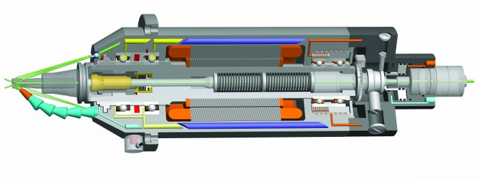 HSK spindles, like the one shown in the illustration above, offer advantages steep-taper styles can't. Image courtesy of IBAG North America. This is the approach taken by BIG KAISER Precision Tooling Inc., Hoffman Estates, Ill. Jack Burley, vice president of sales and engineering, said the BIG-PLUS system—developed in 1992 by BIG Daishowa Seiki Co. Ltd., Osaka, Japan—relies on a bit of elastic deformation in the spindle to provide dual points of toolholder contact at its face and taper, eliminating upward holder movement as the spindle expands. He said it’s also more rigid, with tests showing that the deflection on a CV40 BIG-PLUS toolholder measured at 70mm (2.755") from the spindle face is only 60µm (0.002") when subjected to 500kg (1,102 lbs.) of radial force, roughly half that of a traditional V-flange toolholder.
“There are now roughly 150 machine builders that either offer BIG-PLUS or have it as a standard,” Burley said. “The beauty of the system is that it can use either standard toolholders or BIG-PLUS interchangeably. So for drilling and reaming work, you can use a conventional collet chuck, but for heavy milling cuts or profiling operations at higher spindle speeds, BIG-PLUS improves accuracy and tool life.” Revving UpBurley does not recommend BIG-PLUS for older machines that have never seen these toolholders, because CAT and BT taper-only contact holders tend to bellmouth the spindle over time, leading to undesirable results. BIG-PLUS, like any dual-contact toolholder, requires particular attention to cleanliness, as chips caught between the spindle face and the toolholder can cause serious problems. He also recommends staying below 30,000 rpm when using 40-taper holders, noting that higher speeds are better handled by HSK spindles and holders. Keep It Clean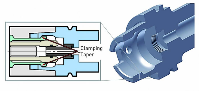 The clamping mechanism for HSK toolholders is distinctly different from that of steep-taper holders. Image courtesy of BIG KAISER Precision Tooling. Bill Popoli, president of IBAG North America, North Haven, Conn., said the company started building steep-taper spindles in the late ’80s, but 95 percent of its work has since transitioned to HSK spindles. As mentioned earlier, the extreme accuracy needed to guarantee near-simultaneous contact between the spindle face and taper is challenging, requiring micron-level tolerances in toolholder and spindle alike. These requirements were impossible to meet when steep taper was first developed, Popoli said, resulting in looser standards overall for CAT and BT spindles than the ones applied to HSK spindles and toolholders. Because of this, purchasing an HSK or equivalent toolholder automatically makes one “part of the club” when it comes to balance, accuracy, repeatability and tool life. That’s not to say, however, that shops firmly married to steep tapers should settle for less. Popoli recommends purchasing the highest-quality tooling possible and paying close attention to the stated tolerance.
Always stay below 20,000 rpm with 40-taper holders, and reach no more than 30,000 rpm with 30-taper ones. Use balanced holders and high-quality retention knobs that have been properly torqued—otherwise distortion at the small end of the taper may occur. And whatever the taper type, keep the spindle and toolholder clean at all times. Bob Freitag agreed. The manager of application engineering at Minneapolis-based metalworking products and services provider Productivity Inc. said the lines are evenly split between traditional 40- and 50-taper CAT or BT tooling (much of which is BIG-PLUS) and HSK. “It really depends on the application,” Freitag said. “Most of our die and mold machines in the 20,000- to 30,000-rpm range will have an HSK63A or HSK63F. When you get up around 45,000 rpm, you’re probably looking at an HSK32. But in horizontal machining centers and lower-rpm, high-torque verticals, you’ll see mostly steep tapers, as this is generally preferred for deep depths of cut and lower feed rates, where you’re removing a lot of material at once.” For shops that want to make the leap to an HSK machine but are leery of investing in new toolholders, Freitag advised: “Anytime you buy a new machine, you should buy new toolholders to go with it. If not, the imperfections of the old toolholders will soon transfer themselves to the spindle on the new machine.”  Remember to replace your spindle cleaners on a regular basis so that you aren't using worn out cleaners. What you think is helping to preserve your valuable Machine Tool/Presetter might actually be hurting it. When replaced regularly, spindle cleaners can prolong the life of your machine, tools & holders, and tool cleaners enhance the repeatability to the machine spindle. This is a perfect example of how a small investment can make a big impact. 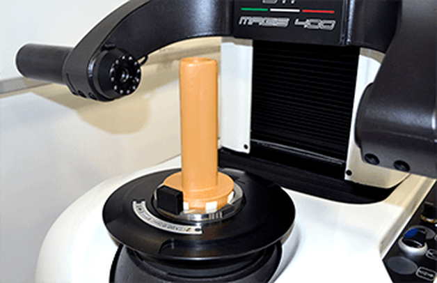 We are very excited to announce that we are now able to offer on-site technical training to YOUR machinists at YOUR location! This is offered at no charge to customers who use any of the manufacturer's whom we represent in California and Nevada. However, just because you don't purchase things from us, don't feel left out! We also offer on-site topic specter training on any of the following topics for $150/hour. Each presentation lasts about 2 hours. The presentations last approximately 45-60 minutes with the remaining time for Q&A and discussion about unique applications in your facility.  Training Classes Available: Machining 101
Advanced Part Manufacturing:
 In order to get the maximum life out of your Steep taper rotary toolholders in your CNC milling machines, follow these best practices that you can implement in your shop. Perhaps not all of them can be implemented every day or every time but it's well worth being aware of how to best protect your investment.
|
Technical Support BlogAt Next Generation Tool we often run into many of the same technical questions from different customers. This section should answer many of your most common questions.
We set up this special blog for the most commonly asked questions and machinist data tables for your easy reference. If you've got a question that's not answered here, then just send us a quick note via email or reach one of us on our CONTACTS page here on the website. AuthorshipOur technical section is written by several different people. Sometimes, it's from our team here at Next Generation Tooling & at other times it's by one of the innovative manufacturer's we represent in California and Nevada. Archives
July 2024
Categories
All
|
 RSS Feed

About
|
© 2024 Next Generation Tooling, LLC.
All Rights Reserved Created by Rapid Production Marketing
|
