|
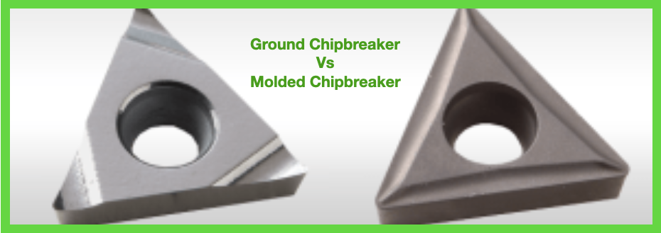
A common question asked for boring operations is when would I use a ground chip-breaker vs. a molded chip-breaker? A ground chip-breaker is recommended for chip control issues. The high-positive rake angle will help to make shorter chips, and the chip groove orientation forces the chips forward to more easily evacuate them from the bore, especially when used with high-pressure coolant through the tool. Ground chip-breaker inserts also provide lower cutting forces, so they are better suited for deep-boring or long-reach applications, and other situations where part or tool stability may not be optimal. Ground chip-breakers are also recommended for tight-tolerance applications where stock allowance is typically light for the final size pass. A molded chip breaker is recommended for stable applications in short-chipping materials. Because these situations don’t require a super-sharp edge for cutting the material, these inserts hold their edge longer for better tool life, and in most cases are less expensive. A Primer on Types of Chips
0 Comments
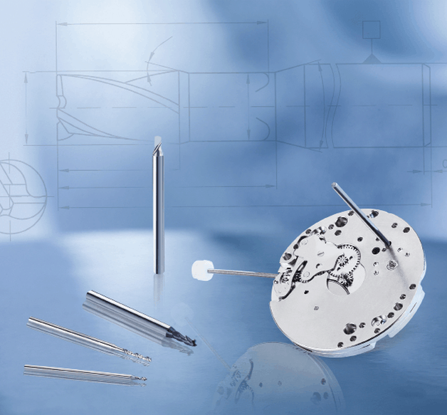
About the author: Jack Burley, Vice President of Sales and Engineering and Big Kaiser Precision Tooling Inc. Micromachining, cutting where the volume of chips produced with each tool path is very small, is not a high-speed operation in relation to chip load per tooth. Rather, it involves a high spindle speed relative to cutter diameter. The part may be physically larger, but details of the part require ultra-small profiles achieved only by micromachining. In other words, micromachining is not limited in scope to only miniature parts. TOOLHOLDING In medical work, where tight tolerances are standard, dynamic runout; the measurement of the spindle at high speeds, performed using laser or capacitance resistance technology, and balance must be controlled to deliver and maintain viable tool life.
A holder with 0.00060" runout accuracy produced nearly two-thirds fewer holes, only 800. In this scenario, the shop could save hundreds of dollars a month in carbide costs – as well as labor costs due to less tool changing – by making one smart tool holder choice. Holder attributes that can boost production include symmetrical design, a perfectly concentric collapse of the collet around the cutter, and a ball-bearing raceway nut with precision-ground threads. CHALLENGES While these characteristics are good rules of thumb, things change fast in this field and, like our customers, we must adapt as trends emerge. Batch sizes are getting smaller. Bone screws, for example, were typically run on multi-axis, Swiss-type lathes where the same tools and programs ran for days at a time. Traditionally, prototyping in this arrangement was not an option because of the complexity and time involved in programming and setup. Today’s need for customized sizes demands flexibility and quick changeover to remain productive. We are investing a large portion of our research and development (R&D) in tackling this challenge. We are working on hydro-clamping tool holder systems that could make the decades-long approach of using ER collets obsolete. It would make it possible, for example, to perform a simple drill change on a gang slide in seconds. COOLANTS Another trend in medical manufacturing being driven by the U.S. Food and Drug Administration (FDA) is clean machining without the use of water-soluble coolants.
We are focusing on two features:
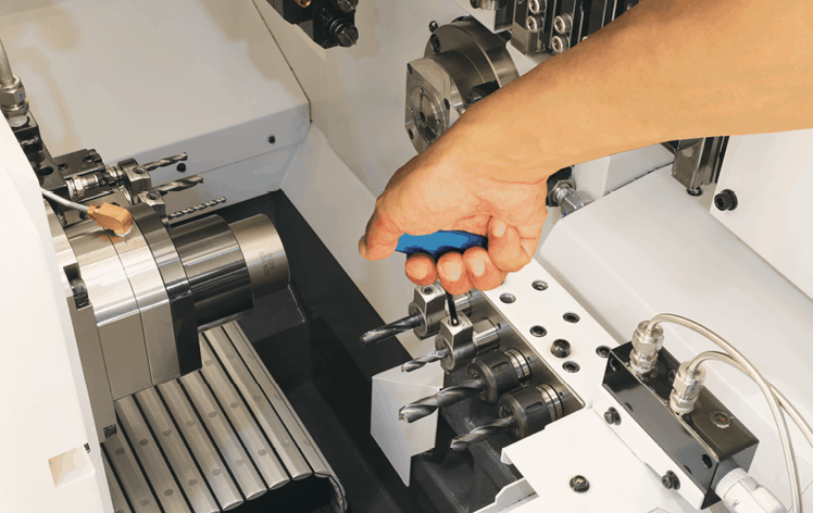
TOOLING Tool considerations also must be taken into account to keep up with the demanding medical field. Better results often cannot be achieved by simply increasing spindle speeds or using smaller tools; a deeper understanding of cutters is necessary. We consider tools with diameters <3mm to be micro tools. These aren’t simply smaller versions of their macro counterparts. They have geometric considerations all their own. For example, the 1mm Sphinx drill can run at 80xD. But this is only possible because the cylindrical shaping extends further down the tool, closer to the tip, to facilitate pecking and maintain strength. Tool carbide should be ultra-fine grain (nano or submicron grain size) to ensure high abrasion resistance and good toughness. Coatings are valuable too, but it’s important to understand how coatings can negatively impact micro tool performance. Micro tools have extremely fine surface finishes and sharp cutting edges. Coatings can fill in valuable space – a flute on a drill, for example – needed for proper chip evacuation, which is critical in these applications. Coatings must be ultra-thin (<1µm) and smooth; our experience shows that misapplied coatings result in poor tool life due to breakage; the coating reduces cutting edge sharpness, increasing torque force on the drill. When coating is necessary, consult with the cutting tool manufacturer to provide this directly. Chips and small tooling naturally do not get along well. Compensating for low spindle speeds with tools that have more flutes support an ideal feed rate, but chip evacuation may suffer. Determining the appropriate chip load – as close to the cutting edge as possible – allows operations at the highest possible spindle speed, accelerating the cycle and improving surface finish. Optimal conditions exist when the chip load is relatively equal to the cutting edge radius. Many micro end mills are designed so the cutting edge radius has a positive rake angle to create a shearing action. A chip load less than the cutting edge radius often results in a negative rake angle where the tool rubs rather than cuts. This increases the force required and generates more heat which can result in built-up edges and poor tool life. A chip load significantly bigger than the cutting edge radius often leads to premature failure because the tool is not robust enough to withstand such forces. MACHINE TOOLS
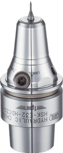
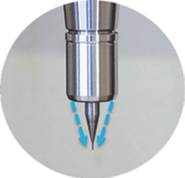
Micromachining requires machine tools with very high sensitivity, fine resolution in the feed axis, and very precise spindles capable of high speed with low dynamic runout. For micro-drilling operations, specialized micro machines are best. Micro milling machines are suited for small tools and small workpieces. They are characterized by spindle speeds faster than 50,000rpm using small HSK tool holders such as HSK-E32, E25, or E20. With the right holder, tool runout can be controlled to less than 1µm (0.000040") at the cutting edge, ensuring sub-micron accuracy. In medical micromachining, understanding each piece of the equipment puzzle is critical. It’s also important not to make assumptions based on other tools or parts you may have worked with, especially in more standard sizes. Invest the right time and energy in gearing up for the next medical job and you’ll get more parts done right faster. |
Technical Support BlogAt Next Generation Tool we often run into many of the same technical questions from different customers. This section should answer many of your most common questions.
We set up this special blog for the most commonly asked questions and machinist data tables for your easy reference. If you've got a question that's not answered here, then just send us a quick note via email or reach one of us on our CONTACTS page here on the website. AuthorshipOur technical section is written by several different people. Sometimes, it's from our team here at Next Generation Tooling & at other times it's by one of the innovative manufacturer's we represent in California and Nevada. Archives
July 2024
Categories
All
|
About
|
© 2024 Next Generation Tooling, LLC.
All Rights Reserved Created by Rapid Production Marketing
|

 RSS Feed
