|
Technical Blog excerpt courtesy of Techniks USA 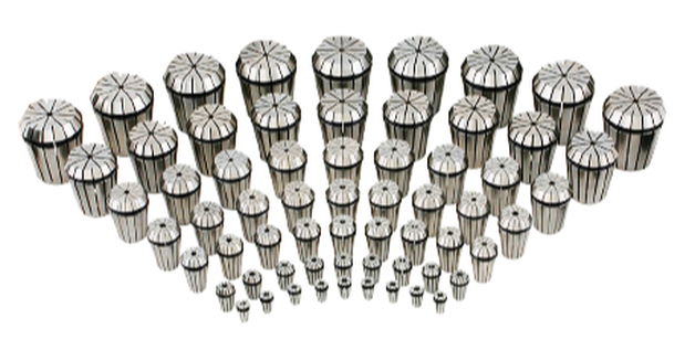 Techniks offers the broadest selection of ER collets including standard, steelsealed, coolant, rigid & floating tap, and DNA - Dead Nuts Accurate, collets. It is important to understand how collets work, what impacts their performance, how to maintain collets for long service life, and how to recognize when to replace them. Collets are a high-precision wear component of a tool holding system and require maintenance to ensure accuracy. First, it’s important to remember that collets are the softest component in a collet-based tool-holding system assembly and are designed to wear out. Here is an overview of the wear pattern of a collet-based tool-holding system. The machine spindle is harder than the tool holder/collet chuck that fits into the spindle, so any wear between these two components will mostly occur to the collet chuck. That’s good. It protects the spindle from expensive maintenance. Collets are softer than both the collet chuck body and the cutting tool, so any wear forces between these items will mostly occur to the collet. Since collets are generally the least expensive component in a collet chuck tool holding system, it is preferred that the collets wear out before the other components. Worn-out collets will not achieve the same level of accuracy and rigidity that newer collets can provide. The result is more chatter when cutting workpieces, less accuracy, and shorter cutting tool life. When to Replace ColletsCollets are designed to wear out as they lose accuracy and rigidity with use. High side-load forces during milling operations cause cutting tool deflection as illustrated below. 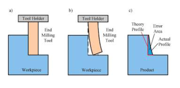 Over time, these side-load forces will bell-mouth the collet at its face. 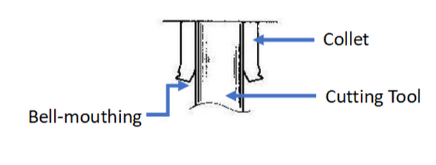 As the collet experiences bell-mouthing, the cutting tool is allowed to deflect more and more during milling operations. Unfortunately, the collet may still indicate good accuracy on a presetter where there are no side-load forces. However, once the tool is put into service and begins experiencing side-load forces, the cutting tool is allowed more room to deflect, resulting in increased chatter and reduced tool life. It is recommended to change collets out every 4-6 months, depending on usage, to ensure the most rigid and accurate collet chuck assembly. A good rule of thumb is to replace collets every 4-6 months to maximize the performance of your tooling. Again, collets are designed to wear out and are generally the least expensive component in the system. It is much less expensive to replace the collets as opposed to prematurely wearing out cutting tools. The following tips will help you in maintaining collets:
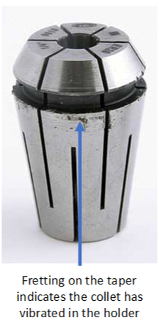
Signs that Your Collet Should be Replaced
If you see signs of fretting on the collet, it is advised to replace the collet. You should also ensure that collet nuts are tightened to the correct torque specifications during setup.
CLICK HERE to see all of our more in-depth articles on FRETTING to learn more.
0 Comments
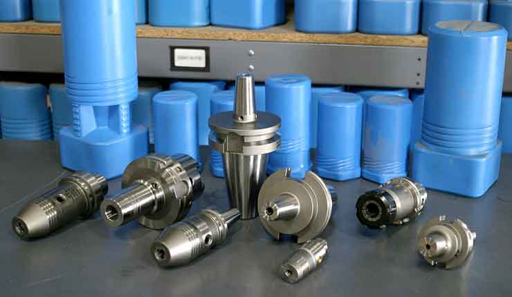
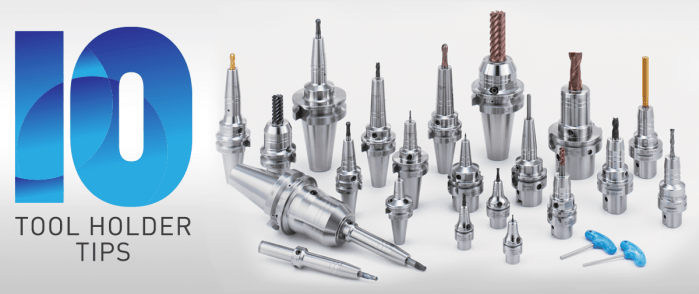 The four critical requirements for tool holders are clamping force, concentricity, rigidity, and balance for high-spindle speeds. When these factors are dialed in just right, there’s nearly no chance of holder error and considerable cost reduction is achieved thanks to longer tool life and reduction of down-time due to tool changes. Easier said than done, our experts shared some of their best, quick-hitting advice for top tool holder performance in different situations. 1. Balance holders as a complete assembly Long-reach milling has some unique demands; when setting up this type of job, always balance tool holders as a complete assembly. While many tooling providers pre-balance their holders at the factory, it’s often inadequate, especially for long-reach applications. 2. Holder damage can go from bad to worse quickly Wear and tear on holders can be costly in the end, but there are ways to protect against it. Inspect and care for your holders. Trauma on a holder or spindle—dings, scratches, gouges, etc.—can magnify quickly. One bad holder can spread its problems like an illness. If you’re seeing disruptions like these on your holders, get them out of the rotation. 3. The rule of thumb on holder dimensions Looking for affordable ways to avoid vibration? Start by opting for a holder with a combination of the largest diameter and shortest length possible. 4. Rigidity can harm tapping operations What many don’t realize about tapping operations is that a perceived strength of collet chucks—their rigidity—can actually be detrimental. Rigidity does very little to counteract the dramatic thrust loads imposed on the tap and part, exacerbating the already difficult challenge of weathering the stop/reverse and maintaining synchronization. 5. Balancing is crucial to five-axis machining Five-axis machining introduces a whole new set of tooling challenges. While important in any type of machine, balance may be of most importance in full five-axis work. A well-balanced holder helps ensure the cutting edge of the end mill must be consistently engaged with the material in order to prevent chatter and poor surface finish quality. 6. Consider spindle speed requirements when choosing between shrink-fit and hydraulic holders If you have to choose between shrink-fit and hydraulic holders in a long-reach application, consider the spindle speed required. If a hydraulic chuck exceeds its rated RPM, fluid is pulled away from the holder’s internal gripping gland, causing loss of clamping force. But when used within its recommended operating range, a hydraulic tool holder offers superior runout and repeatability. On average, a good shrink-fit holder has about 0.0003-inch runout, while a hydraulic chuck offers 0.0001 inch or better. 7. Don’t overlook the tool’s effect on holder performance The cutting tool affects holding ability more than most machinists and engineers realize:
8. Not all dual-contact tooling is the same Anyone in the market for BIG-PLUS dual-contact tooling should consider this simple statement: Only a licensed supplier of BIG-PLUS has master gages that are traceable to the BIG grand master gages and have the dimensions and tolerances provided to make holders right. Everyone else is guessing and using a sample BIG-PLUS tool holder as their own master gage—a practice that any quality expert will advise against. Look for the marking: “BIG-PLUS Spindle System-License BIG DAISHOWA SEIKI.” 9. You may have a BIG-PLUS spindle and not even know it You’d be surprised how often we hear from our certified regrinders or engineers in the field about folks that didn’t realize their machine had a BIG-PLUS spindle—the message can get lost in the supply chain or during the sales process. The easiest way to know if an interface is BIG-PLUS is to place a standard tool into the spindle and see how much of a gap there is between the tool holder flange face and spindle face. Without BIG-PLUS, the standard gap should be visible, or about 0.12 in. If it is BIG-PLUS, the gap is half of this amount, or only 0.06 in. These values change depending on 30 taper, 40 taper or 50 taper sizes, but the gap is visibly less than usual. 10. Use positive offsets during holder setup It may be how it’s traditionally been done but touching off holder assemblies in each machine to establish negative tool offsets based on the zero-point surface—the vise, machine table, workpiece, etc.—is not the most efficient process. We think the choice is pretty clear: adapting machines to a single presetter so they can receive positive gage lengths is superior to using all types of machine-specific negative offsets.
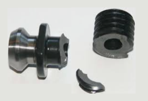
This is a change to “the way things have always been done” that can be met with some resistance, but in the grand scheme of things, it’s a relatively small and simple step that makes life much easier. It’s a relatively low-cost opportunity to introduce more standardization of holder setup to the shop floor. Holders are the bridge between the machine and the part. That’s a lot of pressure—literally and figuratively. It’s important to select, care for and use holders carefully from the day they are purchased until they’re tossed into the recycling bin. From collet chucks to coolant inducers, BIG KAISER is North America’s source for standard-bearing tool holders that guarantees high performance. Explore the full lineup. by Bernard Martin There have been some who claim that drawbar gripper fingers and/or ball marks that appear on retention knob head after several tool changes is normal. 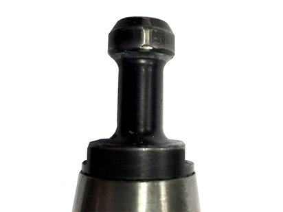 It is NOT.
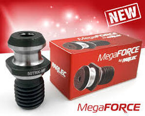
THAT IS FALSE. According to Haas CNC, ball or gripper marks on the edge of the pull stud indicate that the drawbar does not open completely. If you see these indication marks you should check your drawbar and replace these pull studs immediately. by Bernard Martin Retention Knobs are the critical connection between your machine tool and the tool holder and they are the only thing holding a steep taper tool holder in the machine’s spindle. Techniks has recently introduced their MegaFORCE retention knobs that have some rather unique features when compared to standard pull studs. Before delving into the features of the MegaFORCE pull studs, let's review some things that you may not know, or think about, on a daily basis.
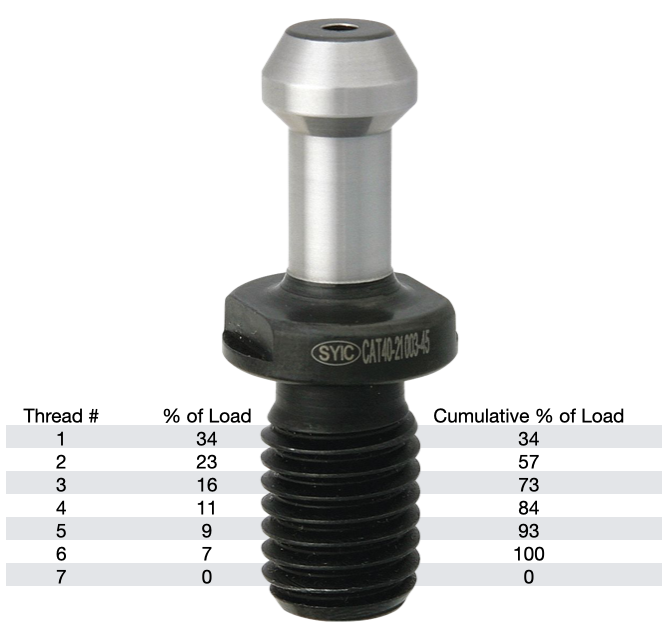
According to Haas, you should expect a service life of about 6000-8000 hours for a retention knob. Most all rotary toolholder manufacturers state that you should be replacing your pull studs at least every three years. However, if you're running multiple shifts, 24-7, making lots of tool changes, making very heavy cuts with long reach or heavy cutting tools, and/or have ball lock style grippers instead of collet type grippers used on the retention knob, you will probably need to replace your studs at least every six months. Given the spindle speeds that we are running at to remain competitive, retention knobs are not an item that you want to take a chance on breaking. I can tell you firsthand that 5 pound toolholder with a drill in it flying out of the spindle at 23,000 RPM is not something you want to experience. METAL FATIGUE: WHY THEY FAILPull studs encounter catastrophic failure as a result of metal fatigue. The metal fatigue can be caused by a number of reasons including poor choice of base material, engineering design, machining process, poor heat treatment, and, sometimes, they have just met or exceeded their service life. We're going to dig into each of these reasons below but first let's look at some threading fundamentals.
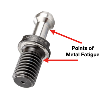
The load on each subsequent thread decreases from there, as show in the table. Any threads beyond the first six are purely cosmetic and provide no mechanical advantage. Additional threads beyond the sixth thread will not further distribute the load and will not make the connection any stronger. That is why the length of engagement of the thread on a pull stud is generally limited to approximately one to one & a half nominal diameter. After that, there is no appreciable increase in strength. Once the applied load has exceeded the first thread's capacity, it will fail and subsequently cause the remaining threads to fail in succession. RETENTION KNOB DESIGNRepetitive cycles of loading and unloading subject the retention knob to stress that can cause fatigue and cracking at weak areas of the pull stud. What are the weak areas of a standard retention knob?
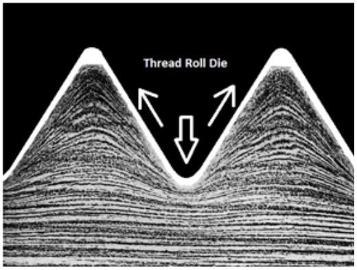
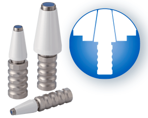
The most common failure point for a retention knob is at the top of the first thread and the underside of the pull stud where the grippers or ball bearings of the drawbar engage and draw the toolholder into the spindle. Remember, bigger Radii are stronger than sharp corners. More on that soon. 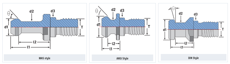 Styles of MegaFORCE Retention Knobs MATERIALNot all retention knobs are made from the same material, however, material alone does not make for a superior retention knob. Careful attention to design and manufacturing methods must be followed to avoid introducing potential areas of failure. Techniks MegaFORCE retention knobs are made from 8620H. AISI 8620 is a hardenable chromium, molybdenum, nickel low alloy steel often used for carburizing to develop a case-hardened part. This case-hardening will result in good wear characteristics. 8620 has high hardenability, no tempering brittleness, good weldability, little tendency to form a cold crack, good maintainability, and cold strain plasticity. There are some companies making retention knobs from 9310. The main difference is the lower carbon content in the 9310. 9310 has a tad more Chromium, while 8620 has a tad more nickel. Ultimate Tensile Strength (UTS) is the force at which a material will break. The UTS of 8620H is 650 Mpa (megapascals: a measure of force). The UTS of 9310H is 820 Mpa. So, 9310H does have a UTS that is 26% greater than 8620H. That said, Techniks chose 8620 as their material of choice because of the higher nickel content. Nickel tends to work harden more readily and age harden over time which brings the core hardness higher as the pull stud gets older. The work hardening property of 8620 makes it ideally suited for cold forming of threads on the MegaFORCE retention knobs. It should be noted that some companies are using H13. H13 shares 93% of their average alloy composition in common with 9310. ROLLED THREADS VS. CUT THREADS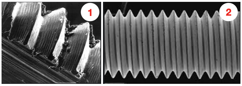 A cut thread, image 1, has a higher coefficient of friction due the the cutting process, while a roll formed thread, image 2, has a lower coefficient of friction which means that it engages deeper into the toolholder bore when subjected to the same torque. You will notice that Cutting threads tears at the material and creates small fractures that become points of weakness that can lead to failure. Rolled threads have burnished roots and crests that are smooth and absent of the fractures common in cut threads. Rolled threads produce a radiused root and crest of the thread and exhibit between a 40% and 300% increase in tensile strength over a cut thread. The Techniks MegaFORCE retention knobs feature rolled threads that improve the strength of the knob by 40%.
Also, unlike thread cutting, the grain structure of the material is displaced not removed.
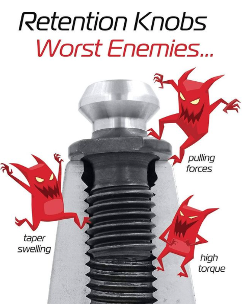
By comparison, cut threads interrupt the grain flow creating weak points. MEGAFORCE GEOMETRIC DESIGN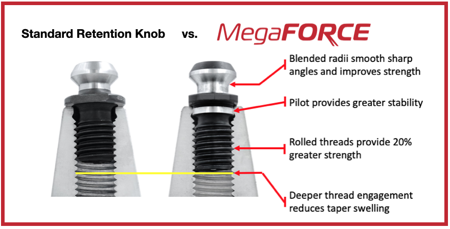 Overall Length There are some claims that a longer projection engages threads deeper in the tool holder preventing taper swelling. While a deeper thread engagement can help prevent taper swelling, applying proper torque to the retention knob is an effective way to reduce taper swelling. An over-tightened retention knob may still cause taper swelling regardless of how deep it engages the threads of the tool holder. Additionally, the longer undercut section above the threads presents a weak point in the retention knob.
Ground Pilot There is a ground pilot, underneath the flange, which provides greater stability. The pilot means the center line of the tool holder and pull stud are perfectly aligned. Magnetic Particle Tested Each Techniks MegaFORCE retention knob is magnetic particle tested to ensure material integrity and physical soundness. MegaFORCE retention knobs are tested at 2.5X the pulling forces of the drawbar.
RETENTION KNOB BEST PRACTICESIn order to maximize the life of your retention knob and prevent catastrophic failure here are some technical tips to keep your shop productive and safe.
Special thanks for Greg Webb at Techniks and Mike Roden from Fette Tools/ Turning Concepts, for providing technical insights.
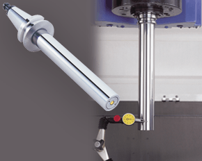
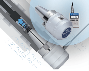
A machine’s spindle is one of the key links in the machining chain. In other words, if there are irregularities inside or at the face, they can show up on your part. It makes regular inspection and spindle maintenance critical to getting the most out of your equipment and maintain process efficiency. These three accessories, the Dyna Contact Taper Gage, the Dyna Test Bar and the Dyna Force Measurement Tool, can help you perform this maintenance easily without eating into valuable spindle time. Dyna Contact Taper Gage
Dyna Test Bar
With the help of a dial indicator, you can uncover any runout while safely spinning the spindle at a very low RPM and verify the parallelism of Z-axis motion. Dyna Force Measurement Tool
The Dyna Force measurement tool provides a precise digital reading that reveals reduction in retention force in increments of 0.1kN. If you would like a demonstration for any of these tools contact us or set up an appointment for one of our Next Generation Tooling engineers to visit you!
 Remember to replace your spindle cleaners on a regular basis so that you aren't using worn out cleaners. What you think is helping to preserve your valuable Machine Tool/Presetter might actually be hurting it. When replaced regularly, spindle cleaners can prolong the life of your machine, tools & holders, and tool cleaners enhance the repeatability to the machine spindle. This is a perfect example of how a small investment can make a big impact. 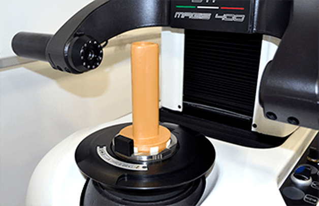 We are very excited to announce that we are now able to offer on-site technical training to YOUR machinists at YOUR location! This is offered at no charge to customers who use any of the manufacturer's whom we represent in California and Nevada. However, just because you don't purchase things from us, don't feel left out! We also offer on-site topic specter training on any of the following topics for $150/hour. Each presentation lasts about 2 hours. The presentations last approximately 45-60 minutes with the remaining time for Q&A and discussion about unique applications in your facility.  Training Classes Available: Machining 101
Advanced Part Manufacturing:
 In order to get the maximum life out of your Steep taper rotary toolholders in your CNC milling machines, follow these best practices that you can implement in your shop. Perhaps not all of them can be implemented every day or every time but it's well worth being aware of how to best protect your investment.
|
Technical Support BlogAt Next Generation Tool we often run into many of the same technical questions from different customers. This section should answer many of your most common questions.
We set up this special blog for the most commonly asked questions and machinist data tables for your easy reference. If you've got a question that's not answered here, then just send us a quick note via email or reach one of us on our CONTACTS page here on the website. AuthorshipOur technical section is written by several different people. Sometimes, it's from our team here at Next Generation Tooling & at other times it's by one of the innovative manufacturer's we represent in California and Nevada. Archives
July 2024
Categories
All
|
 RSS Feed

About
|
© 2024 Next Generation Tooling, LLC.
All Rights Reserved Created by Rapid Production Marketing
|
