|
A Swiss type CNC automatic lathe and a CNC lathe, they are similar lathe machines, but did you know they are completely different? In this article, the kind folks at NTK Cutting Tools will introduce the 4 differences between the cutting tools used based on the mechanical structure of Swiss CNC automatic lathes and CNC lathes. What is the difference between a “Swiss CNC Automatic Lathe” and a “CNC lathe”?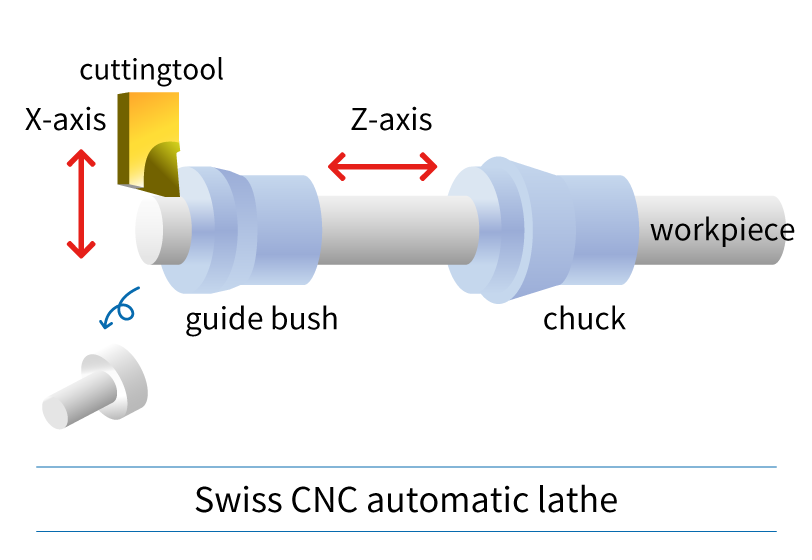
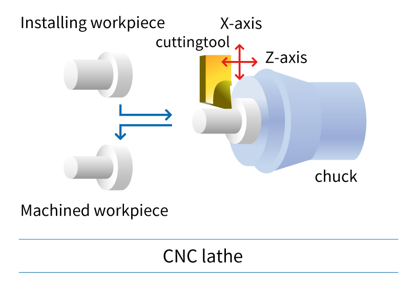
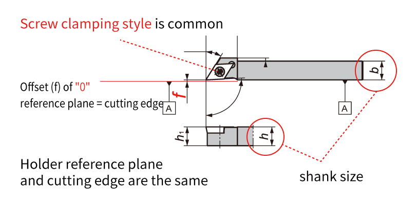
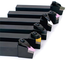
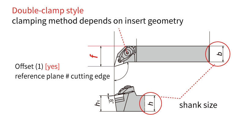
Swiss CNC automatic lathe & CNC lathe: Since the machine structure, workpiece, and size are different, it is important to select the cutting tool accordingly. Now let's take a look at the features of cutting tools used in CNC automatic lathes. Difference 1. HolderThe holder is an important component for achieving chip performance. I will explain the difference between the holder used on a Swiss type CNC automatic lathe and a CNC lathe.
Holders for Swiss CNC Automatic Lathe
CNC Lathe Holders
Difference 2. Insert geometry: Positive inserts and Negative insertsCNMG... DNMG...: If you are familiar with machining on CNC lathes, you likely know about insert geometries. The Swiss type CNC automatic lathe is the same type of lathe, but if you are thinking of machining with the same insert, be careful! Inserts such as "CNMG /CNGA..." and "DNMG/DNGA ..." used on CNC lathes have many corners, and the cutting edge is honed or chamfered (edge preparation) and have excellent cutting edge strength. These inserts are ideal for shearing the workpiece material. On the other hand, when a negative insert such as "CNMG/CNGA..." is used on a Swiss type CNC automatic lathe, cutting resistance tends to be high and "chatter" and "work deflection" occur. We recommend using a "positive style" for Swiss CNC automatic lathes. Swiss-type CNC automatic lathes machine workpieces that are smaller in diameter and require higher precision than machining on a CNC lathes. High cutting resistance causes “vibration” and “dimensional defects”, so using a “positive insert” with a relief angle to reduce cutting resistance and achieve stable machining. 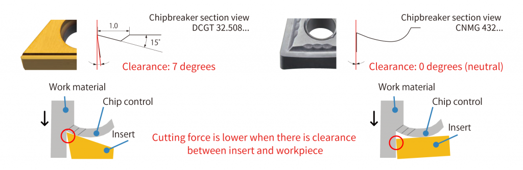 As shown above, the larger the clearance angle (relief), the smaller the area where the tool touches the workpiece. This reduces cutting resistance. b Difference 3. Insert tolerance: G-class and M-class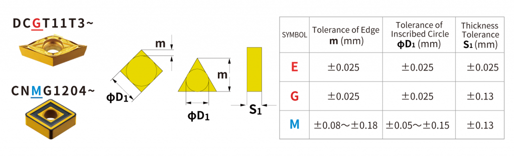 The ISO insert designation includes a tolerance class. I will discuss the difference in insert tolerance classes for Swiss type CNC automatic lathes and CNC lathes. The table above compares the “M” class commonly used on CNC lathes with the “G” class and “E” class commonly used on Swiss SNS automatic lathes. The 3rd letter in the insert part description identifies the tolerance class. Insert such as CNMG… and DNMG… have an M class tolerance. On the other hand, inserts such as DCGT… and CCGT… have a G-class tolerance. As shown in the table, the insert tolerance is very different between the “G” and “M” class. Corner length (m) and insert IC (dia. D1) tolerance affect the accuracy of the cutting edge position, or workpiece dimensions. Thickness tolerance (S1) affects the height of the cutting edge. Swiss-type CNC automatic lathes require high precision machining of small diameter workpieces, so “G-class” or “E-class” with higher tolerance than M-class are used. Also, the upper and lower insert surfaces of G-class and E-class inserts are polished and the outer edges are ground with high accuracy which achieves excellent sharpness. For Swiss CNC automatic lathes, it is strongly recommended to use inserts with “G-grade” and “E-class” tolerances. 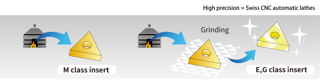 Difference 4. Coatings types: PVD vs. CVDCoating is an important factor in determining the performance of tools and the quality of workpieces. There are two main types of coatings - CVD and PVD. Which coating is suitable for Swiss CNC automatic lathes? 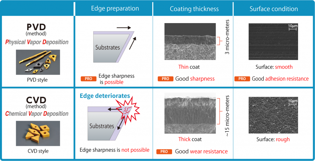 Inserts like “CNMG” and “DNMG” used on CNC lathes are generally CVD coated. CVD coatings can be thick films compared to PVD coatings and have excellent abrasion resistance. But, because it is a thick film coating, it is easy to cause deterioration and there is a disadvantage of a rough coating surface. Swiss-type CNC automatic lathe machining requires high precision, sharpness is important, so PVD coatings are more suitable due to thin film coatings achieving sharp edges. As shown in the figure above, PVD coatings have excellent sharpness, dimensional stability, and welding resistance making it the ideal coating style for Siwss-type CNC automatic lathes. Do you still have questions about the difference between tooling used for a Swiss type CNC lathe and traditional CNC lathe?
NTK offers a large lineup of tools specialized for CNC automatic lathes. If you are having issues machining, please consider contacting us for technical advise.
4 Comments
A very helpful article from our friends at NTK Cutting Tools.  When you hear the word “ceramic”, the first thing people may think of is the “white” material used for plates and sanitary ware (toilets). But that type of ceramic is just one of a number of ceramics. There are as many as five ceramics used for cutting tools.In this article, we will introduce the 5 types of ceramic used in cutting tools. What is ceramic in the first place?IIn a broad sense, ceramics are a blend of metal or nonmetal with oxygen (O), nitrogen (N), carbon (C), etc., and this baked material is used as a cutting tool. The ceramic used in cutting tools is roughly available in two types of “Alumina ceramic” (Al2O3) and “silicon nitride (Si3N4) ceramic” made by blending various additives with the main ingredients to develop specific characteristics. It is further subdivided by the addition of various additives to the main ingredients. Al2O3 : Alumina-based ceramics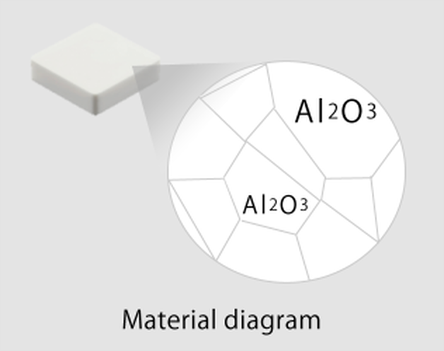 1. White Ceramic Alumina (Al2O3) is the main component of ceramic, and is called white ceramic because of its color. In fact, the same ingredients are in jems like rubies and sapphires (Al2O3) The main difference is that ruby and sapphire are single crystals (particles of one large mass), while alumina is polycrystalline (a collection of multiple particles). Alumina is hard and chemically stable. Taking advantage of its properties, it is used in high-speed finishing of cast iron. 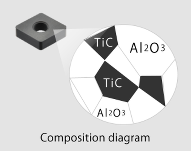 2. Black Ceramic Titanium carbide (TiC) is added to alumina, and this is called black ceramic because of its color. The addition of titanium carbide results in higher hardness, than white ceramic, and suppresses deformation of the cutting edge due to heat; even at high temperatures. Taking advantage of its properties, it is used in high-speed finishing of hardened materials up to about HRC65. 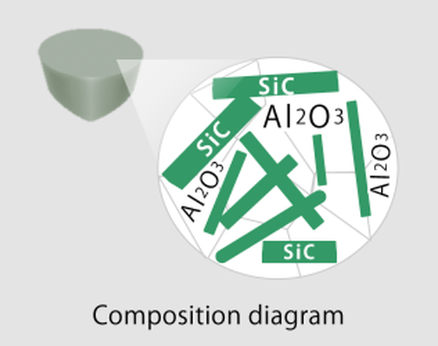 3. Whisker It is a ceramic in which silicon carbide (SiC) is added to alumina. Do you know why it’s called whisker ? Silicon carbide has a needle-like shape similar to a “animal beard”, so it is now called whisker (ceramic). By intertwining silicon carbide with each other, the progression of cracks due to impacts during cutting is suppressed, and cracks are prevented. In addition, it has a resistance against sudden temperature changes. Taking advantage of these properties, it is widely used for heat-resistant alloy processing. Silicon nitride, Si3N4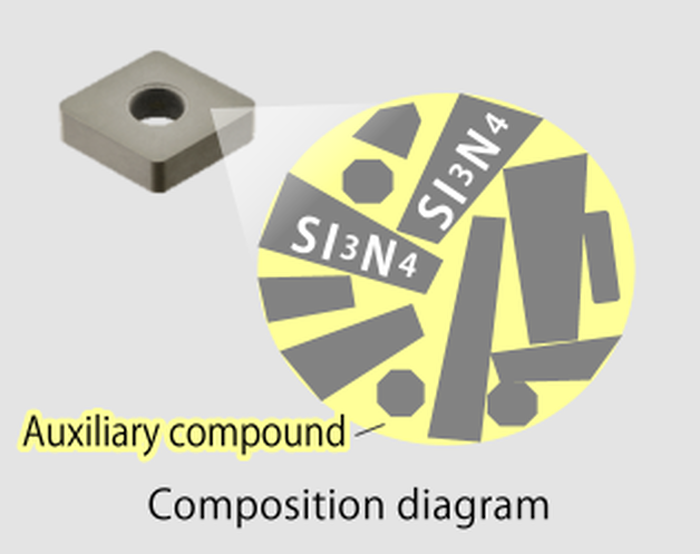 5. Silicon Nitride Silicon nitride (Si3N4) is the main component, and a special feature is that the particles are needle-like, different from the alumina compound. By intertwining needle-like particles, the progression of cracks due to impact during cutting can be greatly suppressed, preventing cracks. Taking advantage of these properties, it is used in high-speed roughing of cast iron. 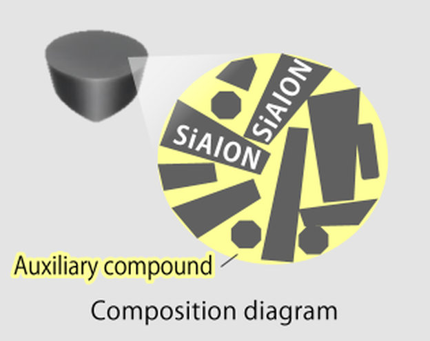 5. Sialon Silicon nitride (Si3N4), Aluminum (Al), and oxygen (O)are blended to form SiAlON, which is an initial of its component elements. Sialons, like silicon nitride, have needle-like particles. Needle-like particles intertwine to withstand impact during cutting. In addition, the effect of the added alumina component improves heat resistance over silicon nitride, and has excellent high temperature resistance characteristics. Taking advantage of these properties, it is used in high-speed processing of heat-resistant alloys. The table below shows typical machining application examples of ceramic cutting tools.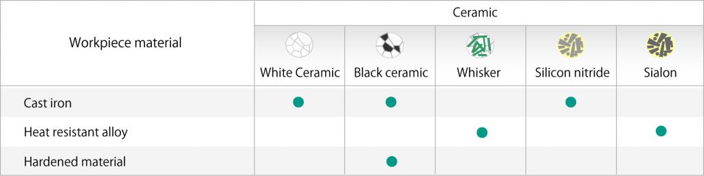 We hope this column gave you a better understanding of the types, differences, and features of ceramic materials.
Ceramic cutting tools must be used according to the material to be machined, but they can be processed up to 20 times faster than carbide tools. Increase productivity with ceramic cutting tools for your material applications.  Here are some simple quick tips when you are machining machining hard materials.
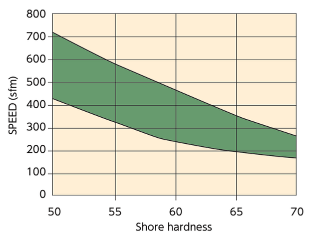 Hard Turning Speed SFM chart based upon a material's Shore Hardness.. As the hardness increases the SFM decreases. 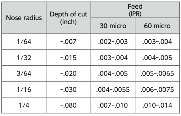 Some good rules of thumb for Hard Turning: The IPR Feed Rate is based upon ceramic insert nose radius and Depth of Cut (DOC) 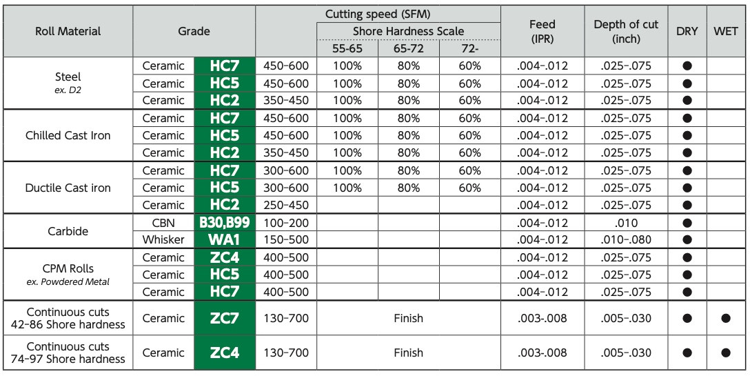 Best choice of ceramic insert grades for use in hard turning from NTK NTK CeramiX HX5 replaces CBN 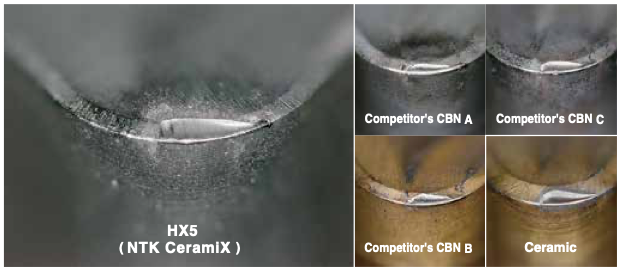 NTK developed this latest game changing ceramic material NTK CeramiX HX5 to replace CBN. As a ceramic cutting tool specialist, NTK has been researching new advancements for ceramics in the industry for decades. They recently introduced a new grade that matches CBN on performance. The new CeramiX "HX5" grade provides a cost saving solution for hard turning applications. It's designed for Hard Turning with continuous cut in the Hardness range of 55 to 66HRc 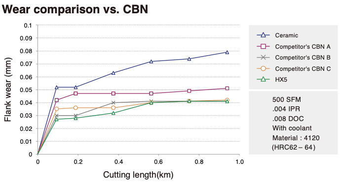 NTK HX5 CeramiX Wear Comparison to Competitors CBN. This chart corresponds to the photos above.
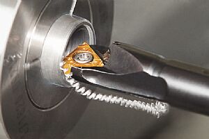
NTK offers an extensive line of high precision boring tooling designed for Swiss machines. One of these produce lines is called “Mogul Bar”. The Mogul Bar system provides the user outstanding chip control and higher rigidity than most conventional tooling on the market. 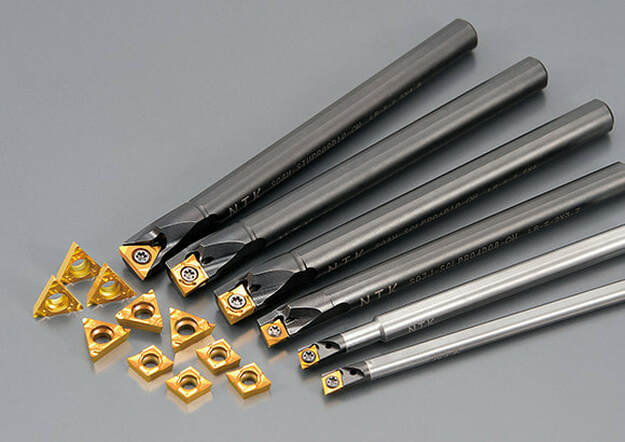 Outstanding chip evacuationThe most notable characteristics of the Mogul Bar is excellent chip evacuation and chip control. Mogul Bars outfitted with NTK’s “F” or “FG” chipbreaker inserts will evacuate chips backwards. This means that when a Mogul Bar machines an I.D. bore, chips comes out towards the bore entrance. The major-ity of boring processes on Swiss machines are done on the main spindle side and thus the bore itself is a blind hole. This machining process creates many issues if you use conventional boring bars designed for CnC lathes. Typical difficulties incurred during a boring process on Swiss machines are either chips remaining in the bore and rough surfaces caused by inconsistent chip control. However, Mogul Bars equipped with nTK uniquely designed chipbreakers, evacuate chips straight backwards and solves both of these problems at once.
Excellent Rigidity Another important feature of the Mogul Bar series is high rigidity. Mogul Bars increased rigidity is a result of a newly designed bar head configuration and a minimal flat width on the bar. Steel shank Mogul Bars can machine as deep as L/D=5, a depth which nor-mally requires expensive carbide shank boring bars. NTK carbide shank Mogul Bars can machine up to L/D=7 depth and this gives users flexibility of machin-ing deeper bores in a single process. rigidly and mini-mal flat widths reduce vibration. Variety of Insert Grades NTK offers both coated carbide grades and cermet insert grades for Mogul Bars. As most tooling engineers know, cermet grades can machine at faster speeds with higher productivity, provide better sur-face finishes and can achieve more accurate dimen-sion control, than carbide grades. These benefits come from the fact that the primary substrate of cermet grades, Tin /TiC, are chemically stable compared with WC of carbide grades and have better adhesion resistance. Mogul Bars are available from a minimum machining diameter of 5mm. With the combination of NTK unique chipbreakers, you can enjoy better chip control and highly rigid boring bars. In comparison with solid carbide boring tools, Mogul Bars has cost advantage as well. If you are facing chip control or chattering issues, NTK believes that Mogul Bars can be the answer to your problems. 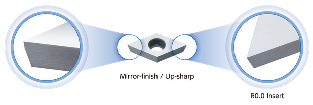 NTK KM1 Grade Mirror Finish Insert for Front & Back Turning, Cut-off, Grooving / Side Turning, and Threading A trend that we are seeing develop in many industries, especially in the medical implant device manufacturing sector, is a rise in the number of parts being manufactured from plastics such as Peek. Polyether ether ketone (PEEK) is a colourless organic thermoplastic polymer in the polyaryletherketone (PAEK) family. It was originally introduced by Victrex PLC, then Imperial Chemical Industries in the early 1980s. Its important to note that PEEK is a thermoplastic. This polymer is capable of being repeatedly softened by an increase in temperature. Increasing the temperature leads to a physical change. That's why cutting tool pressure and heat will impact surface finish and tool life. The medical industry has found medical-grade PEEK offers excellent strength, wear resistance and biocompatibility for components such as the dental healing caps, spiked washers and spinal implants. 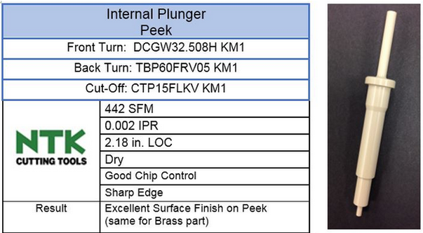 PEEK polymer is available in two basic grades: industrial and medical: "Industrial-grade PEEK is a strong thermoplastic that retains its mechanical properties even at elevated temperatures. The flame-retardant material is abrasion resistant, has high impact strength and a low coefficient of friction. Industrial-grade PEEK components are used in the aerospace, automotive, chemical, electronics, petroleum, and food and beverage industries. Medical-grade PEEK possesses those same physical properties in addition to biocompatibility, high chemical resistance and compatibility with several different sterilization methods. It is also naturally radiotranslucent when viewed using X-ray, MRI or computer tomography (CT). Medical-grade PEEK provides doctors with an unobstructed view of tissue and bone growth around the PEEK implant during the healing process. Some implantable-grade PEEK polymers have a bone-like stiffness and can remain in contact with blood or tissue indefinitely." 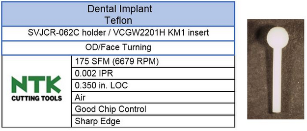 There is also a glass and carbon-fiber-reinforced PEEK, which offer high wear resistance for components such as articulating joints and tends to wear out inserts rather quickly. Peek parts are generally very small, ranging from 0.039" to 0.250" in diameter, which adds to the complexity of machining the non-ferrous materials. Because of the thermoplastic properties, too much heat at the cutting edge results in Built Up Edge (BUE) and tool pressure affects part tolerance. That where NTK's KM1 grade insert work great. The inserts are extremely up-sharp edge and the mirror insert surface creates excellent surface finishes. 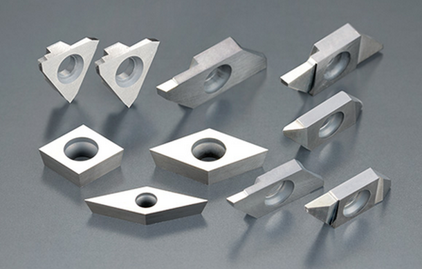 NTK KM1 Uncoated grade for CNC Turning Peek
Things to Remember when Cutting Peek
Keys to Succesfull Machining of Peek1. Limiting Heat Build-up – The softening or melting temperatures of engineering plastics are roughly 1/10th those of metals. 2. Melting or Scorching– The thermal conductivity of plastics is low relative to metals. Most of the heat generated by machining will stay at the surface. Temperatures at the surface can rinse unexpectedly high. 3. Loss of Tolerance – If the overall temperature of the stock changes during or after machining, expansion or contraction can cause the part to fall out of tolerance. Softening of the stock can allow it to deflect at the surface under the pressure of the cutting tool. When the pressure is removed, the stock will recover and fall out of tolerance. This can frequently be managed by using lubricants and changing tooling or speed. 4. Controlling Deflection – Plastics inherently vary in their stiffness (modulus) and are more elastic at higher temperatures. The entire stock can deflect under the pressure of cutting. Proper tooling and support remains important and particular attention should be given to adequately supporting the work. 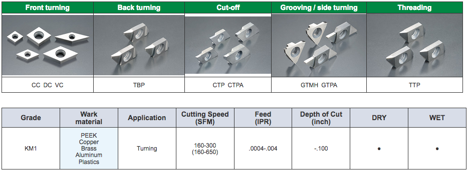 Additional Resources:
NTK Cutting Tools USA launched its first Webinar on 30th January, 2018. The featured presenter is Steve Easterday, NTK's Swiss Product Manager. The topic focuses on chips created during Swiss machining operations and the mainstream concept which is that breaking the chip is important. But is this accurate? NTK has a different concept of Chip Control. The topics covered in the video below include:
How do you break a chip?There are a few different ways to break a chip. Many people tend to think that the best methods of breaking chips in swiss machines are through the use of chip breakers on the inserts, slowing down the speed, increasing the feed, taking a bigger depth of cut and through the use of high pressure coolant. Each one of these, or some combination of them is certainly what is commonly used to gain chip control. 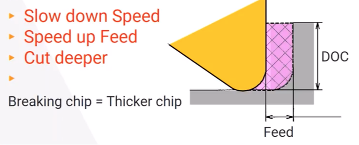 Typically the solution is to reduce the SFM, increase the Feed Rate and increase the Depth of Cut.... but that can lead to workpiece deflection and lower production rates. NTK believes that CONTROLLING the Chips is more important than BREAKING the chips. NTK does this by doing two things:
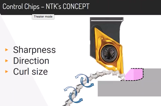 NTK creates a "softer" chip because there is much less heat transferred to the workpiece AND the chips. The translates into better part quality, longer tool life and much more stable machining. Check out the video below for all the details on chip breakers and their toolholder solutions. NTK's industry leading line of ceramic cutting tools recently expanded with new solid CERAMIC end mills! You can see our product announcement here: NTK now offers SX9 Ceramic End Mills for Cutting Exotic Alloys which contains the various features. Below is the technical info on how to run the NTK Ceramic End mills and a troubleshooting guide. NTK's SX9 cermaic end mill grade can run at speeds of 2000 SFM. The line-up includes 4 and 6 flutes in inch and metric versions. Again, you can learn more about on our Blog Post. Solid ceramic end mills are made with SX9 SiAlON grade substrate which features a balance of toughness and wear resistance. It's suitable for even the most demanding applications. 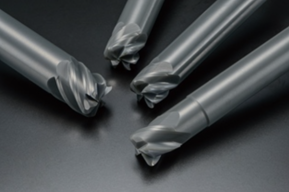 NTK Ceramic end mills with SX9 SiAlON substrate First Step Machining Procedures
Gernarel Recomendations for machining heat resistant alloys & PH stainless steel
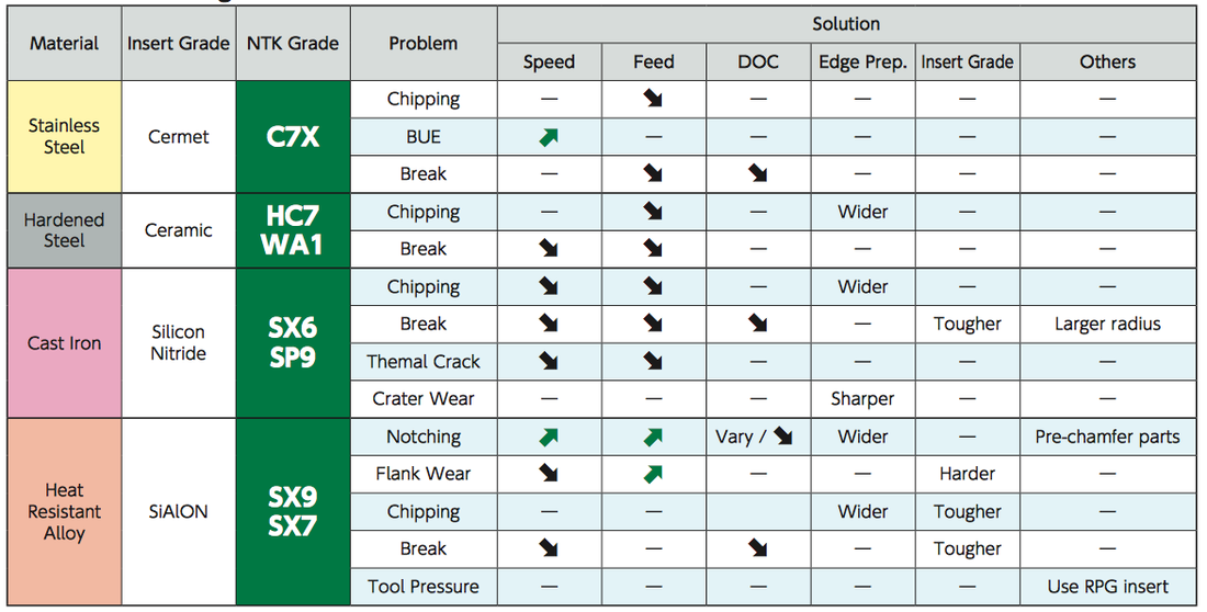 NTK Ceramic end mills Troubleshooting guide As with any other techncial questions please get in touch with us on our CONTACTS page and we can provide both over-the-phone troubleshooting or schedule at time for on-site techncial training.
|
Technical Support BlogAt Next Generation Tool we often run into many of the same technical questions from different customers. This section should answer many of your most common questions.
We set up this special blog for the most commonly asked questions and machinist data tables for your easy reference. If you've got a question that's not answered here, then just send us a quick note via email or reach one of us on our CONTACTS page here on the website. AuthorshipOur technical section is written by several different people. Sometimes, it's from our team here at Next Generation Tooling & at other times it's by one of the innovative manufacturer's we represent in California and Nevada. Archives
July 2024
Categories
All
|

 RSS Feed

About
|
© 2024 Next Generation Tooling, LLC.
All Rights Reserved Created by Rapid Production Marketing
|
