|
By John Zaya, Product Specialist, BIG DAISHOWA—Americas  As the title implies adjusting screws, also known as back-up screws, stop screws and preset screws, are not just a simple set screw. They are a screw with a purpose--three actually. The first is to provide a fixed stop for a cutting tool to rest against during tool changes. This allows an operator to save time as they do not have to pull out a ruler, setting jig, etc. to reassemble the cutter into a holder. A secondary purpose of the adjusting screw is to assist the tool holder in keeping the cutter from being pushed up into the holder if the cutting loads increase to the point where the tool may slip up into the holder. The third is to offer sealing for coolant-through tools. Expected repeatability of cutting tool length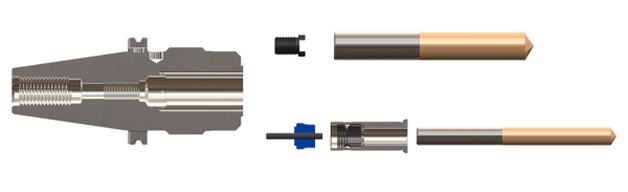 When an old cutter is swapped out and a new one put in its place, the repeatability of this process will vary based on a few parameters such as cleanliness and the OEM cutting tool overall length tolerances. Cleaning the clamping bore or collet of a holder provides better runout repeatability which should be old news to everyone, but if old coolant and contaminants are not removed, they would get jammed between the end face of the shank and the adjusting screw, affecting the length setting. Cutting tool overall length tolerances may also vary from one OEM to another. We have seen them range from ±.3mm to ±.5mm (±.012” to ±.019”). Others may be tighter or looser. Most modern machining centers come with tool length offset measurement systems which will provide the final precise gage length of a tool assembly. With the rough position provided by the adjusting screw, the machine operator can continue working and does not need to worry about tool clearances and stick outs. Forms of adjusting screws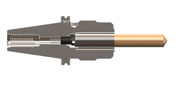 The clamping mechanism of the holder also affects the length repeatability. Both hydraulic chucks and milling chucks are radial clamping systems, whereas a tapered collet is drawn down into a taper by a threaded nut. This draw down causes the cutter to be drawn down as well. For this we have two types of adjusting screws:
Option for adjustable reduction sleeves for MEGA DS/HMC Milling chucks also have a second type of adjustment screw option that can be built into the back end of a reduction sleeve. As cutting tool diameters get smaller, the length of the shank also gets shorter. As such, the end face of the shank may not reach the HMA adjusting screw when installed it the body of the holder. The AC Type Collet adjuster screws into the back end of the reduction sleeve where the shank the tool can easily be reached. Warning on holders that cannot support adjusting screwsIt is always recommended to consult the tool holder catalog or technical documentation to ensure that a holder can support an adjusting screw. Some holders are very short or have very deep internal features that may not allow for the use of any adjusting screw. In those cases, a depth setting ring or collar on the shank of the cutting tool may be an acceptable alternative.
Caution should be used on shrink-fit holders. Thermal expansion/contraction occurs in all three axes, so as the body of a shrink-fit holder cools down it will draw the cutter down jamming onto the adjusting screw. This could lead to damage to the screw, the holder or the cutter.
0 Comments
Edited by Bernard Martin 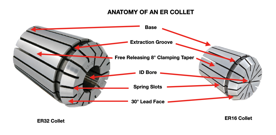 If you work in the metalcutting, signmaking or cabinet making manufacturing industry, the term “collets” is already very familiar to you. There are many types of collets used in many different industries and applications. This article is focused on collets used in rotary tool holders found in CNC milling machining centers and CNC Routers and also used in CNC Lathes and Swiss Style CNC's. Let's cover the basics: What are Collets?Collets are the critical connection between the cutting tool and the tool holder, also called a collet chuck. Most collets are round, cone-shaped, and slotted. Collets encircle the cutting tool shank to evenly distribute holding power around its center bore. Before getting too deep into the technical aspect of collets, It's going to be helpful to anyone new to the use of collets to understand the basic anatomy of collets and of a collet chuck system. How Collets Work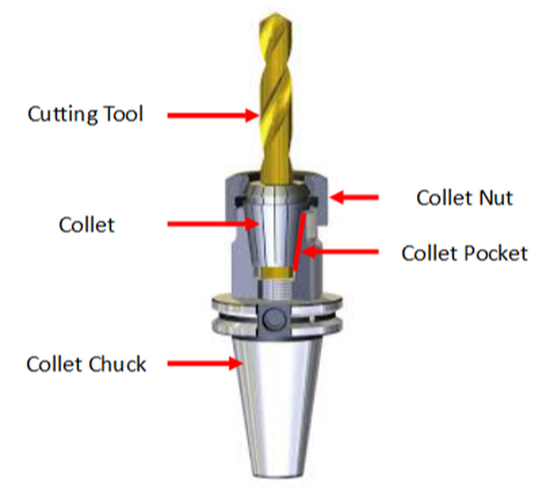 Collet ins depicted being held in a CAT 40 rotary collet chuck toolholder used in CNC milling machines. The tapered collet base is made to fit into the collet pocket of the collet chuck body. The free release locking tapered (16°included, 8° per side) design of the collet base and collet pocket allows the collet to be centered in the pocket as it is pushed in by the collet nut on the lead face during setup.
This centering effect enables the collet to achieve a high degree of accuracy (concentricity); much more than drill chucks and side-lock style end mill holders. As he collet nut is tightened down on the collet, it is pushed into the pocket collet chuck pocket. The slots in the collet allow the I.D. bore to collapse and apply clamping pressure to the cutting tool shank. It's essentially a spring that is compressed tight around the shank of the cutting tool such as a drill or end mill. The result is a very strong and rigid clamping force on the cutting tool. Since the collet base is tapered to match the collet pocket, tool runout (T.I.R.) is reduced. Total indicator runout (TIR) is a term often used in manufacturing, especially when dealing with rotating parts such as cutting tools, particularly endmills and drills. TIR is defined as the difference between the maximum and minimum values measured across an entire rotating surface about a reference axis. 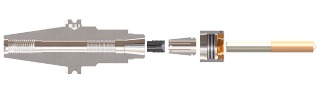 As the title implies adjusting screws, also known as back-up screws, stop screws and preset screws, are not just a simple set screw. They are a screw with a purpose--three actually. The first is to provide a fixed stop for a cutting tool to rest against during tool changes. This allows an operator to save time as they do not have to pull out a ruler, setting jig, etc. to reassemble the cutter into a holder. A secondary purpose of the adjusting screw is to assist the tool holder in keeping the cutter from being pushed up into the holder if the cutting loads increase to the point where the tool may slip up into the holder. The third is to offer sealing for coolant-through tools. 1. Expected repeatability of cutting tool lengthWhen an old cutter is swapped out and a new one put in its place, the repeatability of this process will vary based on a few parameters such as cleanliness and the OEM cutting tool overall length tolerances. Cleaning the clamping bore or collet of a holder provides better runout repeatability which should be old news to everyone, but if old coolant and contaminants are not removed, they would get jammed between the end face of the shank and the adjusting screw, affecting the length setting. Cutting tool overall length tolerances may also vary from one OEM to another. We have seen them range from ±.3mm to ±.5mm (±.012” to ±.019”). Others may be tighter or looser. Most modern machining centers come with tool length offset measurement systems which will provide the final precise gage length of a tool assembly. With the rough position provided by the adjusting screw, the machine operator can continue working and does not need to worry about tool clearances and stick outs. 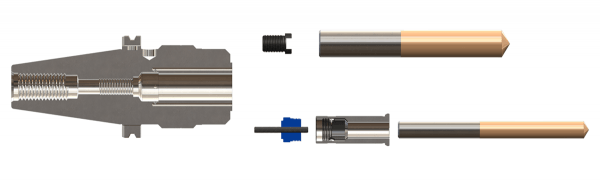 2. Forms of adjusting screwsThe clamping mechanism of the holder also affects the length repeatability. Both hydraulic chucks and milling chucks are radial clamping systems, whereas a tapered collet is drawn down into a taper by a threaded nut. This draw down causes the cutter to be drawn down as well. For this we have two types of adjusting screws: HMA/HDA solid type and NBA rubberized type. The solid type is a one-piece steel construction part, whereas the rubberized type has a rubber padded conical pocket that absorbs the axial travel of the cutter shank as the collet is clamped. 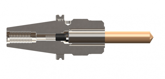 3. Option for adjustable reduction sleeves for MEGA DS/HMCMilling chucks also have a second type of adjustment screw option that can be built into the back end of a reduction sleeve. As cutting tool diameters get smaller, the length of the shank also gets shorter. As such, the end face of the shank may not reach the HMA adjusting screw when installed it the body of the holder. The AC Type Collet adjuster screws into the back end of the reduction sleeve where the shank the tool can easily be reached. 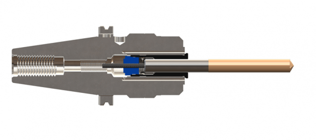 4. Warning on holders that cannot support adjusting screwsIt is always recommended to consult the tool holder catalog or technical documentation to ensure that a holder can support an adjusting screw. Some holders are very short or have very deep internal features that may not allow for the use of any adjusting screw. In those cases, a depth setting ring or collar on the shank of the cutting tool may be an acceptable alternative.
Caution should be used on shrink-fit holders. Thermal expansion/contraction occurs in all three axes, so as the body of a shrink-fit holder cools down it will draw the cutter down jamming onto the adjusting screw. This could lead to damage to the screw, the holder or the cutter. About the author: Jack Burley, Vice President of Sales and Engineering and Big Kaiser Precision Tooling Inc. Micromachining, cutting where the volume of chips produced with each tool path is very small, is not a high-speed operation in relation to chip load per tooth. Rather, it involves a high spindle speed relative to cutter diameter. The part may be physically larger, but details of the part require ultra-small profiles achieved only by micromachining. In other words, micromachining is not limited in scope to only miniature parts. 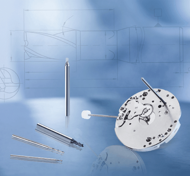 Big Kaiser considers tools with <3mm to be micro tools with unique geometric considerations. TOOLHOLDING In medical work, where tight tolerances are standard, dynamic runout; the measurement of the spindle at high speeds, performed using laser or capacitance resistance technology, and balance must be controlled to deliver and maintain viable tool life.
A holder with 0.00060" runout accuracy produced nearly two-thirds fewer holes, only 800. In this scenario, the shop could save hundreds of dollars a month in carbide costs – as well as labor costs due to less tool changing – by making one smart tool holder choice. Holder attributes that can boost production include symmetrical design, a perfectly concentric collapse of the collet around the cutter, and a ball-bearing raceway nut with precision-ground threads. CHALLENGES While these characteristics are good rules of thumb, things change fast in this field and, like our customers, we must adapt as trends emerge. Batch sizes are getting smaller. Bone screws, for example, were typically run on multi-axis, Swiss-type lathes where the same tools and programs ran for days at a time. Traditionally, prototyping in this arrangement was not an option because of the complexity and time involved in programming and setup. Today’s need for customized sizes demands flexibility and quick changeover to remain productive. We are investing a large portion of our research and development (R&D) in tackling this challenge. We are working on hydro-clamping tool holder systems that could make the decades-long approach of using ER collets obsolete. It would make it possible, for example, to perform a simple drill change on a gang slide in seconds. COOLANTS Another trend in medical manufacturing being driven by the U.S. Food and Drug Administration (FDA) is clean machining without the use of water-soluble coolants.
We are focusing on two features:
 Matching medical components to each patient demands flexibility. This hydro- clamping tool holder system for Swiss-type lathes would make the decades-long approach of using ER collets obsolete by making it possible to perform a simple drill change on a gang slide in seconds. TOOLING Tool considerations also must be taken into account to keep up with the demanding medical field. Better results often cannot be achieved by simply increasing spindle speeds or using smaller tools; a deeper understanding of cutters is necessary. We consider tools with diameters <3mm to be micro tools. These aren’t simply smaller versions of their macro counterparts. They have geometric considerations all their own. For example, the 1mm Sphinx drill can run at 80xD. But this is only possible because the cylindrical shaping extends further down the tool, closer to the tip, to facilitate pecking and maintain strength. Tool carbide should be ultra-fine grain (nano or submicron grain size) to ensure high abrasion resistance and good toughness. Coatings are valuable too, but it’s important to understand how coatings can negatively impact micro tool performance. Micro tools have extremely fine surface finishes and sharp cutting edges. Coatings can fill in valuable space – a flute on a drill, for example – needed for proper chip evacuation, which is critical in these applications. Coatings must be ultra-thin (<1µm) and smooth; our experience shows that misapplied coatings result in poor tool life due to breakage; the coating reduces cutting edge sharpness, increasing torque force on the drill. When coating is necessary, consult with the cutting tool manufacturer to provide this directly. Chips and small tooling naturally do not get along well. Compensating for low spindle speeds with tools that have more flutes support an ideal feed rate, but chip evacuation may suffer. Determining the appropriate chip load – as close to the cutting edge as possible – allows operations at the highest possible spindle speed, accelerating the cycle and improving surface finish. Optimal conditions exist when the chip load is relatively equal to the cutting edge radius. Many micro end mills are designed so the cutting edge radius has a positive rake angle to create a shearing action. A chip load less than the cutting edge radius often results in a negative rake angle where the tool rubs rather than cuts. This increases the force required and generates more heat which can result in built-up edges and poor tool life. A chip load significantly bigger than the cutting edge radius often leads to premature failure because the tool is not robust enough to withstand such forces. MACHINE TOOLS
Micromachining requires machine tools with very high sensitivity, fine resolution in the feed axis, and very precise spindles capable of high speed with low dynamic runout. For micro-drilling operations, specialized micro machines are best. Micro milling machines are suited for small tools and small workpieces. They are characterized by spindle speeds faster than 50,000rpm using small HSK tool holders such as HSK-E32, E25, or E20. With the right holder, tool runout can be controlled to less than 1µm (0.000040") at the cutting edge, ensuring sub-micron accuracy. In medical micromachining, understanding each piece of the equipment puzzle is critical. It’s also important not to make assumptions based on other tools or parts you may have worked with, especially in more standard sizes. Invest the right time and energy in gearing up for the next medical job and you’ll get more parts done right faster.  The four critical requirements for tool holders are clamping force, concentricity, rigidity, and balance for high-spindle speeds. When these factors are dialed in just right, there’s nearly no chance of holder error and considerable cost reduction is achieved thanks to longer tool life and reduction of down-time due to tool changes. Easier said than done, our experts shared some of their best, quick-hitting advice for top tool holder performance in different situations. 1. Balance holders as a complete assembly Long-reach milling has some unique demands; when setting up this type of job, always balance tool holders as a complete assembly. While many tooling providers pre-balance their holders at the factory, it’s often inadequate, especially for long-reach applications. 2. Holder damage can go from bad to worse quickly Wear and tear on holders can be costly in the end, but there are ways to protect against it. Inspect and care for your holders. Trauma on a holder or spindle—dings, scratches, gouges, etc.—can magnify quickly. One bad holder can spread its problems like an illness. If you’re seeing disruptions like these on your holders, get them out of the rotation. 3. The rule of thumb on holder dimensions Looking for affordable ways to avoid vibration? Start by opting for a holder with a combination of the largest diameter and shortest length possible. 4. Rigidity can harm tapping operations What many don’t realize about tapping operations is that a perceived strength of collet chucks—their rigidity—can actually be detrimental. Rigidity does very little to counteract the dramatic thrust loads imposed on the tap and part, exacerbating the already difficult challenge of weathering the stop/reverse and maintaining synchronization. 5. Balancing is crucial to five-axis machining Five-axis machining introduces a whole new set of tooling challenges. While important in any type of machine, balance may be of most importance in full five-axis work. A well-balanced holder helps ensure the cutting edge of the end mill must be consistently engaged with the material in order to prevent chatter and poor surface finish quality. 6. Consider spindle speed requirements when choosing between shrink-fit and hydraulic holders If you have to choose between shrink-fit and hydraulic holders in a long-reach application, consider the spindle speed required. If a hydraulic chuck exceeds its rated RPM, fluid is pulled away from the holder’s internal gripping gland, causing loss of clamping force. But when used within its recommended operating range, a hydraulic tool holder offers superior runout and repeatability. On average, a good shrink-fit holder has about 0.0003-inch runout, while a hydraulic chuck offers 0.0001 inch or better. 7. Don’t overlook the tool’s effect on holder performance The cutting tool affects holding ability more than most machinists and engineers realize:
8. Not all dual-contact tooling is the same Anyone in the market for BIG-PLUS dual-contact tooling should consider this simple statement: Only a licensed supplier of BIG-PLUS has master gages that are traceable to the BIG grand master gages and have the dimensions and tolerances provided to make holders right. Everyone else is guessing and using a sample BIG-PLUS tool holder as their own master gage—a practice that any quality expert will advise against. Look for the marking: “BIG-PLUS Spindle System-License BIG DAISHOWA SEIKI.” 9. You may have a BIG-PLUS spindle and not even know it You’d be surprised how often we hear from our certified regrinders or engineers in the field about folks that didn’t realize their machine had a BIG-PLUS spindle—the message can get lost in the supply chain or during the sales process. The easiest way to know if an interface is BIG-PLUS is to place a standard tool into the spindle and see how much of a gap there is between the tool holder flange face and spindle face. Without BIG-PLUS, the standard gap should be visible, or about 0.12 in. If it is BIG-PLUS, the gap is half of this amount, or only 0.06 in. These values change depending on 30 taper, 40 taper or 50 taper sizes, but the gap is visibly less than usual. 10. Use positive offsets during holder setup It may be how it’s traditionally been done but touching off holder assemblies in each machine to establish negative tool offsets based on the zero-point surface—the vise, machine table, workpiece, etc.—is not the most efficient process. We think the choice is pretty clear: adapting machines to a single presetter so they can receive positive gage lengths is superior to using all types of machine-specific negative offsets.
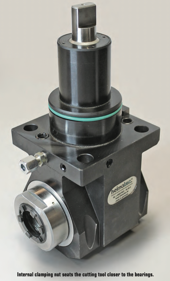
This is a change to “the way things have always been done” that can be met with some resistance, but in the grand scheme of things, it’s a relatively small and simple step that makes life much easier. It’s a relatively low-cost opportunity to introduce more standardization of holder setup to the shop floor. Holders are the bridge between the machine and the part. That’s a lot of pressure—literally and figuratively. It’s important to select, care for and use holders carefully from the day they are purchased until they’re tossed into the recycling bin. From collet chucks to coolant inducers, BIG KAISER is North America’s source for standard-bearing tool holders that guarantees high performance. Explore the full lineup. A REVIEW OF THIS MACHINING METHOD, THE BASIC CONCEPTS AND SOME EXCITING DEVELOPMENTS IN THE TECHNOLOGY by Preben Hansen, President, Platinum Tooling Technologies Inc.  Universal style adjustable tool might be the ideal solution for families of parts. Live tooling, as a component on a lathe, is specifically manipulated by the CNC to perform various milling, drilling and other operations while the workpiece is being held in position by the main or sub spindle. These components, whether BMT or VDI, are also called driven tools, as opposed to static tools, that are used during turning operations. All live and static tools are built per the machine tool builder’s specification for each of the various models they produce. A key to running a successful job shop or production department is to partner with a supplier who can meet the tooling needs for all or most of the machines on your floor. 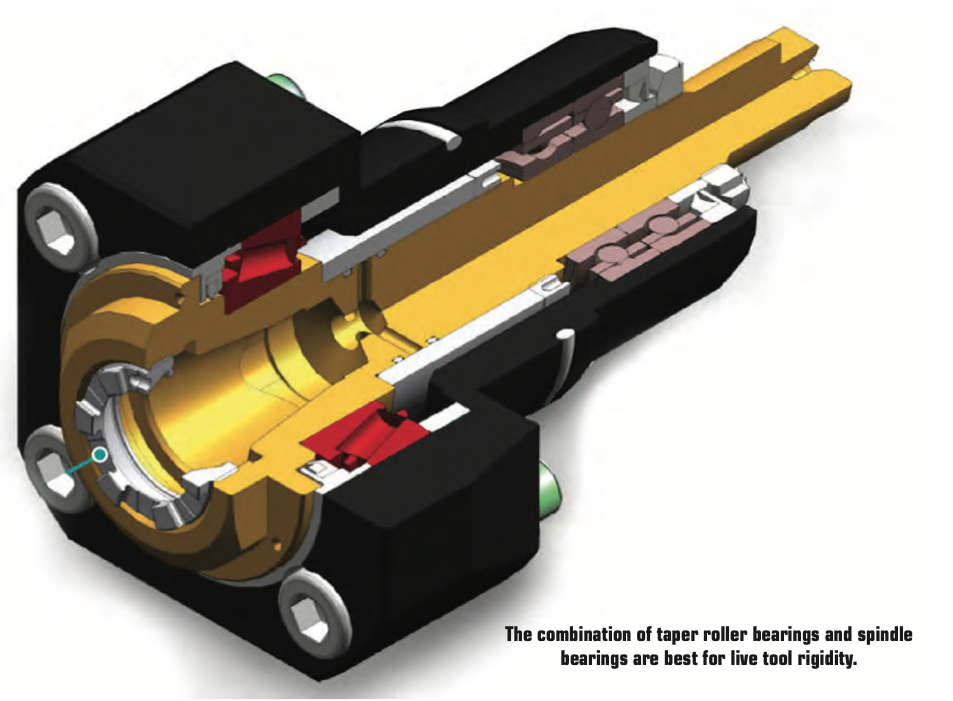 Most often, live tooling is offered in standard straight and 90º angle head configurations with a wide range of tool output clamping systems, including ER collet chuck, arbor, Weldon, Capto, whistle notch, hydraulic, HSK, CAT, ABS and a variety of custom or proprietary systems developed by the many suppliers to the industry. When the need arises for a new machine tool, careful consideration should be made to determine which live tools are appropriate for your application. While a standard machine tool package will help you get started, it is important to anticipate job and volume changes, as well any unforeseen machining challenges from the beginning, in order to avoid machine downtime. This short article is meant to give you a set of parameters to consider when evaluating the live and static tooling to use in your shop or production department. Simply stated, you need to do as much evaluation of your process, when determining the proper tooling to be used, as you did when you evaluated the various machines available for purchase. This fact is often overlooked and that can be a critical error, in the long run. Your examination can range from the simple (external vs. internal coolant, for example) to the sublime (adjustable or multi-spindle configurations) to the custom tool, that may be required and built to suit your special application. Finding a supplier who has an in-house machine shop for the preparation of special tools is a great value-add. Tool life is the product of cutting intensity, materials processed, machine stability and, of course, piece parts produced. Two seemingly identical job shops can have vastly different tooling needs because one is automotive and one is medical, or one specializes in the one-off and low-volume work, while the other has a greater occurrence of longer running jobs. The totality of your operation determines the best tooling for the machines being purchased. Bearing construction and the resulting spindle concentricity drive the life of any tool. You might find that just a 10-15% greater investment in a better design can yield both longer lasting cutters and consistently superior finish on your products. Of course, the stability and rigidity of the machine tool are always critical factors. Bevel and spur gears that are hardened, ground and lapped in sets are best for smooth transition and maximum torque output. Taper roller bearings are consistently superior to spindle bearings in live tool milling applications, so look for a combination system to get the highest rigidity possible. Also, look for an internal vs. external collet nut, so the cutting tool seats more deeply in the tool, as superior performance will result. 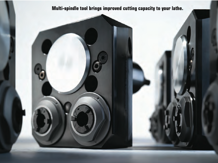 Likewise, high pressure internal coolant might be desirable. Look for 2000 psi capabilities in 90º tools and 1000 psi in straight tools.You need to ask another question, namely, is the turret RPM sufficient to handle the work to be done? It’s possible that a live tool with a built-in speed increaser, often called a speed multiplier, would be helpful. Would it be beneficial to move secondary operations to your lathe? Gear hobbing can be accomplished in this manner, as can producing squares or flats, through the use of polygon machining. Standard live tooling most often is best suited to production work, where the finish, tolerances and cutter life are critical, while quick-change systems may be better suited to the shop producing families of products and other applications where the tool presetting offline is a key factor in keeping the shop at maximum productivity. It’s a given in our industry that when the machine isn’t running, the money isn’t coming.
Dedicated tools for large families of products may often be desirable for some applications, but do consider whether a flexible changing system would be more appropriate. Talk to your tooling supplier for the various options, before making that determination. If standard ER tooling is suitable for the work, there are many good suppliers. It is important though, to pay close attention to the construction aspects noted above. For a quick-change or changeable adapter system, there are fewer suppliers in the market, so seek them out and be sure they can supply the product styles you need for all your lathe brands. 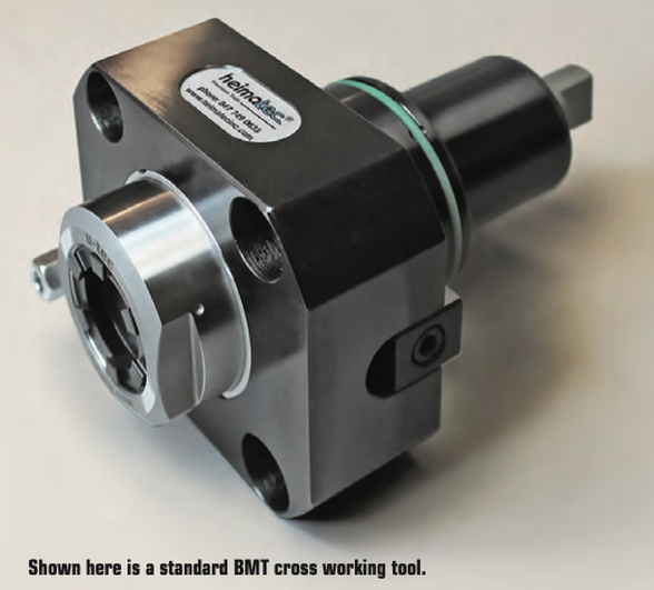 Now, an application example showing clear evidence of the value of testing live tool performance... One company was performing a cross-milling application using an ER 32 output tool on a Eurotech lathe, running 10 ipm at 4000 rpm. They were making three passes with a cycle time of 262 seconds and were having difficulties with chatter on the finish, while producing 20,000 pieces per year. The annual cost of the machining was over $130,000. By using an alternative live tool with an ER 32AX output, internal collet nut design, with the same parameters, they were able to produce the part in a single pass with a smooth finish and cycle time of just 172 seconds. Over the course of the year, this yielded a cost savings of $45,000, approximately 20x the cost of the tool. The bottom line is the bottom line, as the accountants tell us. In the end, you may not need a universal adjustable tool or a multi-spindle live holder or even a quick-change adapter system but do consider all these options. Talk to your machine builder and several tool suppliers, plus the most important people in this equation, your shop personnel, as their input is invaluable to keeping you up and running in a profitable, customer-satisfying scenario. The author welcomes questions, comments and additional input from readers. Please contact Preben Hansen at 847-749-0633 or phansen@platinumtooling.com. Mr. Hansen has over 30 years in tooling and is considered a leading authority on the topic in the North American machine tool market.
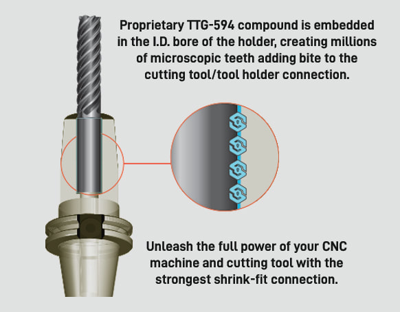
by, Bernard Martin 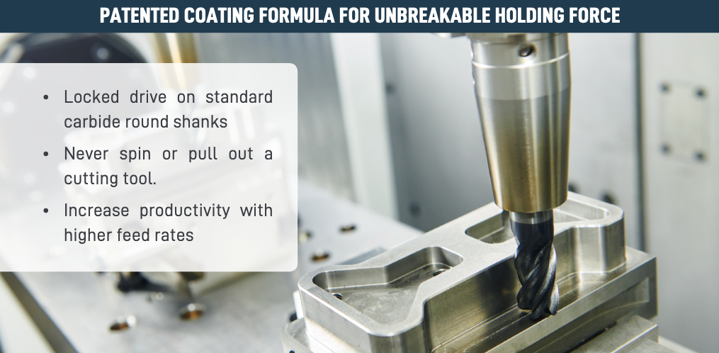 As carbide end mills gain higher and higher speeds and metal removal rates there has also been a trend by round tool manufacturers to tighten up the tolerances on both the cutting diameter and the shank diameter to improve concentricity. At the same time, shrink fit holders have become more and more popular because they hold a tighter concentricity as well. To achieve this both the shank and the bore now have similar surface finishes and this has led to a problem The tools pull out in the cut. Shrink fit holders are the most accurate for TIR as the toolholder engages completely around round shank tools with a bore tolerance of -0.0001" to -0.0003". As high performance end mills have tightened shank tolerances to the same range of -0.0001" to -0.0003" they have used finer and finer grain grinding wheels which give the shanks a 'shiny' appearance. Shiny means that the superfinished shank has a lower coefficient of friction. So, although the TIR is tighter, the shank is more "slippery". End mills traditionally had surface finish of about 8 μin on the tool shank. But that's changed. It's been recommended that tool shanks used in shrink fit holders should not have a finish finer than 16 μin. for optimum holding power, but tell that to the guy who just superfinished the end mill to a super cocncentric tolerance that you don't want it looking that good. Everyone knows that the last thing you want is for the end mill to slip in the middle of a heavy cut or on the finishing pass of a high tolerance part. These 'hi performance' end mills, often times have higher helix angles which are great for ejecting chips but also create a higher pull out force on that slippery shank. And reducing the helix angle is not the answer. We already know that the gripping pressure is a function of the interference between the tool shank and the shrink fit toolholder bore. Most shrink fit holders have a already bore surface finish of between 12 μin. and 16 μin. So they are ground to a very high tolerance and have about the same surface finish as the toolholder shank. End mill manufacturers and machinist have tried a variety of methods over the years to stop the tools from pulling out. This has ranged from grit blasting the shank to rubbing chalk on the shank, but most everyone in the industry has felt that the problem really needs to be addressed by the longer life toolholder rather than the replaceable cutting tool. That's the problem that Techniks wanted to address. Techniks claims that their "proprietary non-slip TTG594 compound virtually fuses the tool shank with the shrink fit toolholder." ShrinkLOCKED Toolholders eliminate cutting tool pull-out and provide 4X the friction drive force compared to un-treated shrink holders.
It’s not just a rougher bore finish that enhances the holding power. TTG-594 is a compound that has a much higher Brinell hardness than carbide so it can “bite” into the tool shank. But this does not affect the ability to perform tool changes. Techniks arrived at their 4x the holding power comes from torsion testing vs. a standard shrink fit toolholder. They used a ¾” carbide gage pin in a standard holder and found the torque at which the tool will spin in the bore. They then tested the ShrinkLOCKED holder using the same test. According to Greg Webb, at Techniks, "We actually could not find the point at which the tool would spin in the ShrinkLOCKED holder as we broke the carbide gage pins at 4x+ times the torque of the standard holder. The holding power is greater, we just have not found a way to measure this, so we kept our claims conservative at 4x."  A guest blog from BIG KAISER. 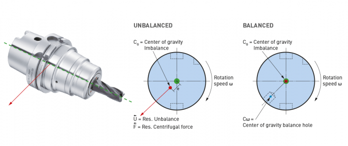 High-speed machining started getting popular in the ‘90s, especially in aerospace where they replaced fabricating processes with machining monolithic parts like wing struts from billets. Machine tools capable of spinning cutting tools at tens of thousands of RPM made it easier to produce these parts quickly. Like machines, holders adapted. The centrifugal forces they had to manage in order to keep tools cutting correctly became extreme. The toolholding systems available at that time were found not to be as effective as the shallower 1-to-10 taper ratio of the German hollow taper shank, hohl shaft kegel (HSK) in German. The HSK has since been standardized to ISO specifications (12164-1, -2). HSK is now available in several sizes and forms to fit with small to large machines. For the most part, the market has settled on the form A for general milling. It has been adopted in Japan, North America and Europe and is truly one of the only worldwide-side toolholder standards. Form E or F is for high-speed machining. The forms have different features depending on the standard they follow. In the end, to achieve efficient tool life, proper finish and productivity in high-speed work, holders need to be as rigid, compact and short as possible to keep the whole assembly stable. What to know when choosing a high-speed tool holder
When it comes to balancing holders, the quality G2.5 is widely used in the industry and is described in the ISO 1940-1 (issued in 2003) standard. However, this quality class is often over-specified and is in many cases not economically or technically feasible, especially when applied to smaller and lighter tools. Standards often applied to tools are more suited for rigid rotors and are practical in a broader use for balancing.
However, it cannot be applied to a complete system of spindles, tool holders and tools adequately and within technical constraints. For example, a tool to be compliant will have to be balanced to less than 1 gmm/kg at a speed of 25,000 rpm, which in turn corresponds to a mass eccentricity of less than 1 μm. This allowable tolerance is less than the interchange accuracy for even HSK, essentially negating all the costs and time for balancing the tool to such a strict tolerance. For this reason, all BIG KAISER tool holders are balanced according ISO 16084 (issued in 2017) specifically developed for rotating tool systems. ISO 16084 focuses on the interaction between spindle and tool factoring in the allowable load on the spindle bearings generated by the tool’s imbalance. This load must not exceed one percent of the dynamic load capacity of the spindle bearings. According to ISO 16084, the allowable unbalance tolerance is specified in [gmm] and is not expressed using a special quality grade [G]. In conclusion, BIG KAISER does not indicate any G-values for balancing quality, but rather the maximum rotational speeds of the individual tool holder. The BIG Kiaser MEGA holder program includes a variety of styles that can be used up to 40,000 RPM. They guarantee 100 percent concentricity and runout accuracy down to .00004" at the nose. They are built specifically to withstand speed and forces required in today’s high-throughput environment. For more information on BIG KAISER's approach to balancing tool holders, click here. To learn more about our high-performance tool holders here. |
Technical Support BlogAt Next Generation Tool we often run into many of the same technical questions from different customers. This section should answer many of your most common questions.
We set up this special blog for the most commonly asked questions and machinist data tables for your easy reference. If you've got a question that's not answered here, then just send us a quick note via email or reach one of us on our CONTACTS page here on the website. AuthorshipOur technical section is written by several different people. Sometimes, it's from our team here at Next Generation Tooling & at other times it's by one of the innovative manufacturer's we represent in California and Nevada. Archives
July 2024
Categories
All
|
 RSS Feed

About
|
© 2024 Next Generation Tooling, LLC.
All Rights Reserved Created by Rapid Production Marketing
|
