 The four critical requirements for tool holders are clamping force, concentricity, rigidity, and balance for high-spindle speeds. When these factors are dialed in just right, there’s nearly no chance of holder error and considerable cost reduction is achieved thanks to longer tool life and reduction of down-time due to tool changes. Easier said than done, our experts shared some of their best, quick-hitting advice for top tool holder performance in different situations. 1. Balance holders as a complete assembly Long-reach milling has some unique demands; when setting up this type of job, always balance tool holders as a complete assembly. While many tooling providers pre-balance their holders at the factory, it’s often inadequate, especially for long-reach applications. 2. Holder damage can go from bad to worse quickly Wear and tear on holders can be costly in the end, but there are ways to protect against it. Inspect and care for your holders. Trauma on a holder or spindle—dings, scratches, gouges, etc.—can magnify quickly. One bad holder can spread its problems like an illness. If you’re seeing disruptions like these on your holders, get them out of the rotation. 3. The rule of thumb on holder dimensions Looking for affordable ways to avoid vibration? Start by opting for a holder with a combination of the largest diameter and shortest length possible. 4. Rigidity can harm tapping operations What many don’t realize about tapping operations is that a perceived strength of collet chucks—their rigidity—can actually be detrimental. Rigidity does very little to counteract the dramatic thrust loads imposed on the tap and part, exacerbating the already difficult challenge of weathering the stop/reverse and maintaining synchronization. 5. Balancing is crucial to five-axis machining Five-axis machining introduces a whole new set of tooling challenges. While important in any type of machine, balance may be of most importance in full five-axis work. A well-balanced holder helps ensure the cutting edge of the end mill must be consistently engaged with the material in order to prevent chatter and poor surface finish quality. 6. Consider spindle speed requirements when choosing between shrink-fit and hydraulic holders If you have to choose between shrink-fit and hydraulic holders in a long-reach application, consider the spindle speed required. If a hydraulic chuck exceeds its rated RPM, fluid is pulled away from the holder’s internal gripping gland, causing loss of clamping force. But when used within its recommended operating range, a hydraulic tool holder offers superior runout and repeatability. On average, a good shrink-fit holder has about 0.0003-inch runout, while a hydraulic chuck offers 0.0001 inch or better. 7. Don’t overlook the tool’s effect on holder performance The cutting tool affects holding ability more than most machinists and engineers realize:
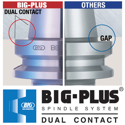
8. Not all dual-contact tooling is the same Anyone in the market for BIG-PLUS dual-contact tooling should consider this simple statement: Only a licensed supplier of BIG-PLUS has master gages that are traceable to the BIG grand master gages and have the dimensions and tolerances provided to make holders right. Everyone else is guessing and using a sample BIG-PLUS tool holder as their own master gage—a practice that any quality expert will advise against. Look for the marking: “BIG-PLUS Spindle System-License BIG DAISHOWA SEIKI.” 9. You may have a BIG-PLUS spindle and not even know it You’d be surprised how often we hear from our certified regrinders or engineers in the field about folks that didn’t realize their machine had a BIG-PLUS spindle—the message can get lost in the supply chain or during the sales process. The easiest way to know if an interface is BIG-PLUS is to place a standard tool into the spindle and see how much of a gap there is between the tool holder flange face and spindle face. Without BIG-PLUS, the standard gap should be visible, or about 0.12 in. If it is BIG-PLUS, the gap is half of this amount, or only 0.06 in. These values change depending on 30 taper, 40 taper or 50 taper sizes, but the gap is visibly less than usual. 10. Use positive offsets during holder setup It may be how it’s traditionally been done but touching off holder assemblies in each machine to establish negative tool offsets based on the zero-point surface—the vise, machine table, workpiece, etc.—is not the most efficient process. We think the choice is pretty clear: adapting machines to a single presetter so they can receive positive gage lengths is superior to using all types of machine-specific negative offsets.
This is a change to “the way things have always been done” that can be met with some resistance, but in the grand scheme of things, it’s a relatively small and simple step that makes life much easier. It’s a relatively low-cost opportunity to introduce more standardization of holder setup to the shop floor. Holders are the bridge between the machine and the part. That’s a lot of pressure—literally and figuratively. It’s important to select, care for and use holders carefully from the day they are purchased until they’re tossed into the recycling bin. From collet chucks to coolant inducers, BIG KAISER is North America’s source for standard-bearing tool holders that guarantees high performance. Explore the full lineup.
0 Comments
by Bernard Martin There have been some who claim that drawbar gripper fingers and/or ball marks that appear on retention knob head after several tool changes is normal. 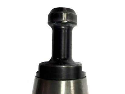 It is NOT.
THAT IS FALSE. According to Haas CNC, ball or gripper marks on the edge of the pull stud indicate that the drawbar does not open completely. If you see these indication marks you should check your drawbar and replace these pull studs immediately. It’s time for machine tool builders and machining companies to shelf the long-standing ISO 1940-1 standard in favor of ISO 16084:2017. Not only is balancing tools rarely necessary, it can also be risky. A lot of conflicting information has circulated over the years about balancing tools. As an author of the new standard for calculating permissible static and dynamic residual unbalances of rotating single tools and tool systems – ISO 16084:2017 – allow me to clear some things up and, hopefully, make life a little easier for you.
Since its institution in 1940, the G2.5 balance specification has been widely accepted across the industry; i.e., “it’s how things have always been done.” However, machines were much slower 80 years ago. Back then, the most advanced machines would have spun larger, heavier tools at a maximum speed of about 4,000 RPM. If you applied the math from those days to today, you’d get unachievable values. For example, the tolerances defined by G2.5 for tools with a mass of less than 1 pound rated for 40,000 RPM calculates to 0.2 gram millimeters (gm.mm.) of permissible unbalance and eccentricity of 0.6 micron. This isn’t within the repeatable range for any balance machine on the market. Similarly, application-specific assemblies, for operations like back boring and small, lightweight, high-speed toolholders, can’t be accurately balanced for G2.5. Machine tool builders rely on an outdated number, too, often basing spindle warranty coverage on using balanced tools at very specific close tolerances. While it’s true that poorly balanced tools run at high speeds wear a spindle faster, decently balanced tools performing common operations won’t wear spindles or tools drastically and deliver the results you’re looking for. While it’s true that poorly balanced tools run at high speeds wear a spindle faster, decently balanced tools performing common operations won’t wear spindles or tools drastically and deliver the results you’re looking for. A Little Lesson About ForcesThis all begs the question: When do you need to take the time to balance holders? I would argue that tools require balancing only if they’re notably asymmetrical or being used for high-speed fine finishing. Here’s a rule I’ve long followed: If cutting forces exceed centrifugal forces due to unbalance, high-precision balancing isn’t needed because the force required to balance the tool will most likely be less than cutting forces.
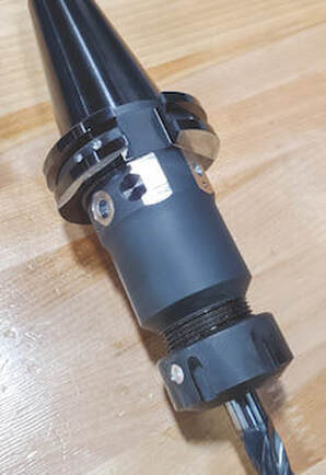
At that point, aggressive cutting – not unbalance – is going to damage the spindle. Unbalanced tools are also blamed for issues that turn out to be misunderstandings about a machine’s spindle. I’ve visited shops with new high-speed spindles that had trouble running micro tools over 15,000 RPM. They rebalanced all the tools on the advice of their machine tool supplier, but to no avail. It turned out the machine was tuned for higher torque and higher cutting forces. Before going to the effort of balancing toolholders, work with your machine builder to understand where a spindle is tuned. Not only is balancing tools rarely necessary, it can also be risky. Our inherently asymmetrical fine-boring heads are a good example. Because we balance them at the center, a neutral position of the work range, you lose that balance if you adjust out or in. To adjust, you’d typically add weight to the light side, which can be a problem for chip evacuation and an obstructor. Or you can remove weight from the heavy side, but that means you have to put some big cuts on the same axis of the insert and insert holder, ultimately weakening the tool. In longer tool assemblies, common corrections made for static unbalance can also cause issues. It happens when a toolholder is corrected for static unbalance in the wrong plane; i.e., adding or removing weight somewhere on the assembly that’s not 180 degrees across from the area where there’s a surplus or deficit. Once the tool is spun at full speed, those weights pull in opposite directions and create a couple unbalance that often worsens the situation.  All the components of Big Kaiser's Mega ER Grip Series - Body, Collet and Collet nut - Are all balanced for high speed machining A Cautionary TaleIf you do go down the balancing road, you’d better know where you can modify tools, what’s inside, how deep you can go, and at what angles. Whether you’re adding or removing material on a holder, I highly recommend consulting the tool manufacturer for guidance first. As a cautionary tale, consider a customer who was attempting to balance a batch of our coolant-fed holders. Based on the balancing machine, the operator drilled ¼-inch holes at the prescribed angle into the body of the holders. Not realizing what was inside, he drilled into cross holes connecting coolant flow and ruined several holders. Tooling manufacturers are doing their part to avert disasters like this. For most, simple tools like collet chucks or hydraulic chucks are fairly easy to balance during manufacturing. We account for any asymmetrical features while machining and grinding holders and pilot each moving part, ensuring they’ll locate concentrically during assembly. These measures ensure the residual unbalance of the assemblies is very, very low and eliminate the need for balancing.
Decades of the same standards have conditioned us to think a certain way about balancing tools. While it seems logical that every tool must be balanced, it’s just not the case: Many issues attributed to unbalance aren’t caused by unbalance, and the risks of balancing every single tool often aren’t worth the reward.
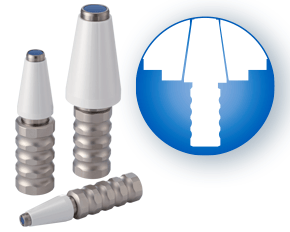
Save your balancing time and resources for high-speed fine finishing. If you do have work where balance is crucial, consider how the tools you buy are balanced and piloted out of the box and/or consult your partners before making any modifications. A machine’s spindle is one of the key links in the machining chain. In other words, if there are irregularities inside or at the face, they can show up on your part. It makes regular inspection and spindle maintenance critical to getting the most out of your equipment and maintain process efficiency. These three accessories, the Dyna Contact Taper Gage, the Dyna Test Bar and the Dyna Force Measurement Tool, can help you perform this maintenance easily without eating into valuable spindle time. Dyna Contact Taper Gage
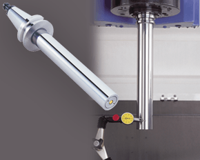
Dyna Test Bar
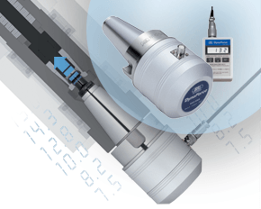
With the help of a dial indicator, you can uncover any runout while safely spinning the spindle at a very low RPM and verify the parallelism of Z-axis motion. Dyna Force Measurement Tool
The Dyna Force measurement tool provides a precise digital reading that reveals reduction in retention force in increments of 0.1kN. If you would like a demonstration for any of these tools contact us or set up an appointment for one of our Next Generation Tooling engineers to visit you!
Below are excerpts from a Cutting Tool Engineering article by the same title. To read the entire article please click HERE.  Author Kip Hanson, Contributing Editor, Cutting Tool Engineering (520) 548-7328 khanson@jwr.com Kip Hanson is a contributing editor for Cutting Tool Engineering magazine. Originally Published: September 12, 2017 - 3:00pm Shopping for a machining center was simpler when buyers had only two basic spindle choices: CAT or BT. Both of these “steep tapers” have an angle of 3.5 in./ft., or 7" in 24" (7/24), and are based on the 1927 patent by Kearney & Trecker Corp., Brown & Sharpe Manufacturing Co. and Cincinnati Milling Machine Co. With the development of automatic toolchangers in the late 1960s, machine tool builders in Japan modified the patented design and invented the BT standard. In the 1970s, tractor manufacturer Caterpillar Inc., Peoria, Ill., changed things again with a flange design now known as CAT, or V-flange. “Sticking” TogetherDuring the late ’80s, machine tool builders began offering vertical and horizontal CNC mills with spindle speeds higher than the 6,000 to 8,000 rpm common at the time. As rpm increased, so did problems with steep-taper toolholders. Chief among them is the tendency for the mating spindle and toolholder tapers to stick together. This is caused by the expansion of the spindle housing at high speeds, which allows the toolholder to be pulled upward into the spindle taper, jamming it in place. HSK spindles, like the one shown in the illustration below, offer advantages steep-taper styles can't. One way to eliminate this problem is by extending the toolholder flange upward, thus creating a hard stop against the spindle face and preventing further Z-axis movement. 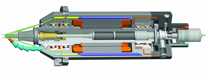 HSK spindles, like the one shown in the illustration above, offer advantages steep-taper styles can't. Image courtesy of IBAG North America. This is the approach taken by BIG KAISER Precision Tooling Inc., Hoffman Estates, Ill. Jack Burley, vice president of sales and engineering, said the BIG-PLUS system—developed in 1992 by BIG Daishowa Seiki Co. Ltd., Osaka, Japan—relies on a bit of elastic deformation in the spindle to provide dual points of toolholder contact at its face and taper, eliminating upward holder movement as the spindle expands. He said it’s also more rigid, with tests showing that the deflection on a CV40 BIG-PLUS toolholder measured at 70mm (2.755") from the spindle face is only 60µm (0.002") when subjected to 500kg (1,102 lbs.) of radial force, roughly half that of a traditional V-flange toolholder.
“There are now roughly 150 machine builders that either offer BIG-PLUS or have it as a standard,” Burley said. “The beauty of the system is that it can use either standard toolholders or BIG-PLUS interchangeably. So for drilling and reaming work, you can use a conventional collet chuck, but for heavy milling cuts or profiling operations at higher spindle speeds, BIG-PLUS improves accuracy and tool life.” Revving UpBurley does not recommend BIG-PLUS for older machines that have never seen these toolholders, because CAT and BT taper-only contact holders tend to bellmouth the spindle over time, leading to undesirable results. BIG-PLUS, like any dual-contact toolholder, requires particular attention to cleanliness, as chips caught between the spindle face and the toolholder can cause serious problems. He also recommends staying below 30,000 rpm when using 40-taper holders, noting that higher speeds are better handled by HSK spindles and holders. Keep It Clean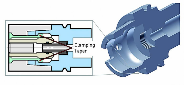 The clamping mechanism for HSK toolholders is distinctly different from that of steep-taper holders. Image courtesy of BIG KAISER Precision Tooling. Bill Popoli, president of IBAG North America, North Haven, Conn., said the company started building steep-taper spindles in the late ’80s, but 95 percent of its work has since transitioned to HSK spindles. As mentioned earlier, the extreme accuracy needed to guarantee near-simultaneous contact between the spindle face and taper is challenging, requiring micron-level tolerances in toolholder and spindle alike. These requirements were impossible to meet when steep taper was first developed, Popoli said, resulting in looser standards overall for CAT and BT spindles than the ones applied to HSK spindles and toolholders. Because of this, purchasing an HSK or equivalent toolholder automatically makes one “part of the club” when it comes to balance, accuracy, repeatability and tool life. That’s not to say, however, that shops firmly married to steep tapers should settle for less. Popoli recommends purchasing the highest-quality tooling possible and paying close attention to the stated tolerance.
Always stay below 20,000 rpm with 40-taper holders, and reach no more than 30,000 rpm with 30-taper ones. Use balanced holders and high-quality retention knobs that have been properly torqued—otherwise distortion at the small end of the taper may occur. And whatever the taper type, keep the spindle and toolholder clean at all times. Bob Freitag agreed. The manager of application engineering at Minneapolis-based metalworking products and services provider Productivity Inc. said the lines are evenly split between traditional 40- and 50-taper CAT or BT tooling (much of which is BIG-PLUS) and HSK. “It really depends on the application,” Freitag said. “Most of our die and mold machines in the 20,000- to 30,000-rpm range will have an HSK63A or HSK63F. When you get up around 45,000 rpm, you’re probably looking at an HSK32. But in horizontal machining centers and lower-rpm, high-torque verticals, you’ll see mostly steep tapers, as this is generally preferred for deep depths of cut and lower feed rates, where you’re removing a lot of material at once.” For shops that want to make the leap to an HSK machine but are leery of investing in new toolholders, Freitag advised: “Anytime you buy a new machine, you should buy new toolholders to go with it. If not, the imperfections of the old toolholders will soon transfer themselves to the spindle on the new machine.” We are very excited to announce that we are now able to offer on-site technical training to YOUR machinists at YOUR location! This is offered at no charge to customers who use any of the manufacturer's whom we represent in California and Nevada. However, just because you don't purchase things from us, don't feel left out! We also offer on-site topic specter training on any of the following topics for $150/hour. Each presentation lasts about 2 hours. The presentations last approximately 45-60 minutes with the remaining time for Q&A and discussion about unique applications in your facility.  Training Classes Available: Machining 101
Advanced Part Manufacturing:
 In order to get the maximum life out of your Steep taper rotary toolholders in your CNC milling machines, follow these best practices that you can implement in your shop. Perhaps not all of them can be implemented every day or every time but it's well worth being aware of how to best protect your investment.
CNC machines feature high-capacity tool changers that automatically swap toolholders in and out of the spindle as needed, by means of a high speed swing arm or a rotary carousel. Periodically, toolholders should be examined for wear and if necessary replaced to maintain cutting performance. 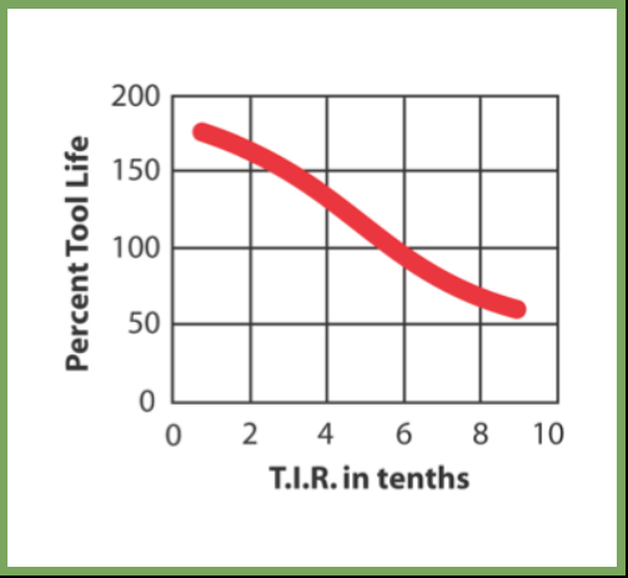 You lose 10% of cutting tool life for every “tenth” (0.0001”) of ru New operators should be taught how to properly evaluate toolholders so they can recognize when toolholders need to be replaced to prevent premature cutting tool failure, or even expensive damage to the spindle. Many operators do not know why it is necessary to replace their tooling, or have the experience to tell when it is time to do so. Determining if toolholder components need to be replaced is not a difficult task, but does require that the operator knows what to look for. Here's a few things you should be aware of when checking your rotary toolholders. Checking For Spindle Mouth Wear 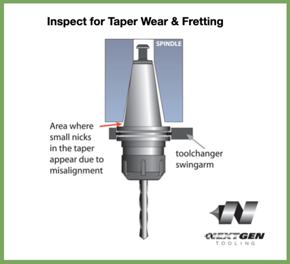 A worn spindle can cause runout issues that affect toolholder accuracy and reduce cutting quality and productivity. This is a condition known as bell mouthing. If toolholder issues can be eliminated by bench checking T.I.R., then the source of the problem is often a worn out spindle mouth. A trained professional will be required to check and repair bell mouthing. T.I.R. (total indicator runout) is the measurement of axial deflection of the cutting tool in the toolholder assembly. Techniks toolholders are manufactured to minimize runout and extend cutting tool life. You lose 10% of cutting tool life for every “tenth” (0.0001”) of runout. That's what the chart above depicts. Automatic Tool Changer Alignment Issues 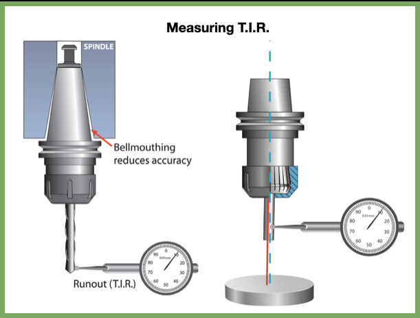 It’s crucial to maintain proper ATC swingarm alignment. If the ATC does not insert the toolholder perfectly, damage to the spindle and toolholder may result. Also poor cutting tool performance and reduced tool life will be evident. A trained professional will be required to check and repair ATC issues. Evaluating Toolholders for Wear A worn out toolholder will not provide good accuracy and will quickly wear out your cutting tools. Worn tooling can also cause poor surface finish, and may even damage your spindle. Keep and eye out for these issues and your tool life, surface finish and cycle time will all improve to help you make more money on every job in your machine shop. Special thanks to TechniksUSA for providing this detailed information! |
Technical Support BlogAt Next Generation Tool we often run into many of the same technical questions from different customers. This section should answer many of your most common questions.
We set up this special blog for the most commonly asked questions and machinist data tables for your easy reference. If you've got a question that's not answered here, then just send us a quick note via email or reach one of us on our CONTACTS page here on the website. AuthorshipOur technical section is written by several different people. Sometimes, it's from our team here at Next Generation Tooling & at other times it's by one of the innovative manufacturer's we represent in California and Nevada. Archives
March 2024
Categories
All
|
 RSS Feed

About
|
© 2024 Next Generation Tooling, LLC.
All Rights Reserved Created by Rapid Production Marketing
|
