|
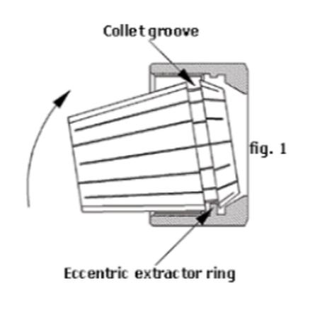
It is critical to properly assemble the collet and collet nut to avoid damage to the collet and make the most accurate and rigid assembly possible. The extraction groove of the collet must be properly seated to the extraction ring of the collet nut.
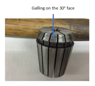
If the collet extraction groove is not properly seated to the collet nut extraction ring, the collet will appear seated below the face of the nut. This typically occurs when the collet is placed in the collet pocket of the tool holder and then the nut is threaded on the tool holder. In a correct assembly, the collet will seat at the face of the collet nut. The image below shows a correct assembly on the left and an incorrect assembly on the right. 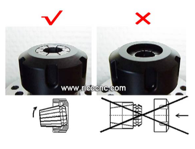 DO NOT tighten the collet nut if the collet appears seated below the face of the nut as this will create galling on the 30° face of the collet. Galling appear as grooves or lines in the lead face of the collet. Recognize Galling on Your ER ColletGalling on the lead face of the collet can result in reduced clamping pressure on the cutting tool shank that may lead to the cutting tool slipping while cutting, or even tool breakage.
0 Comments
Technical Blog excerpt courtesy of Techniks USA 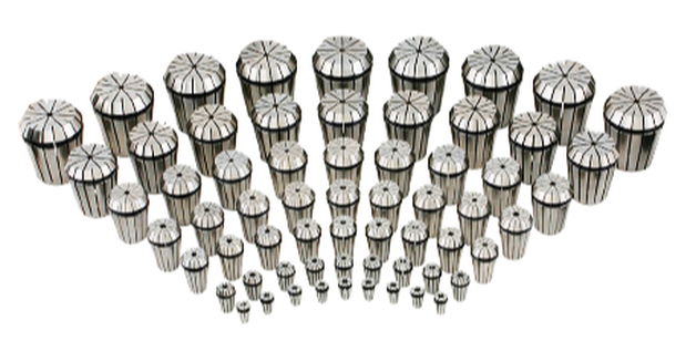 Techniks offers the broadest selection of ER collets including standard, steelsealed, coolant, rigid & floating tap, and DNA - Dead Nuts Accurate, collets. It is important to understand how collets work, what impacts their performance, how to maintain collets for long service life, and how to recognize when to replace them. Collets are a high-precision wear component of a tool holding system and require maintenance to ensure accuracy. First, it’s important to remember that collets are the softest component in a collet-based tool-holding system assembly and are designed to wear out. Here is an overview of the wear pattern of a collet-based tool-holding system. The machine spindle is harder than the tool holder/collet chuck that fits into the spindle, so any wear between these two components will mostly occur to the collet chuck. That’s good. It protects the spindle from expensive maintenance. Collets are softer than both the collet chuck body and the cutting tool, so any wear forces between these items will mostly occur to the collet. Since collets are generally the least expensive component in a collet chuck tool holding system, it is preferred that the collets wear out before the other components. Worn-out collets will not achieve the same level of accuracy and rigidity that newer collets can provide. The result is more chatter when cutting workpieces, less accuracy, and shorter cutting tool life. When to Replace ColletsCollets are designed to wear out as they lose accuracy and rigidity with use. High side-load forces during milling operations cause cutting tool deflection as illustrated below. 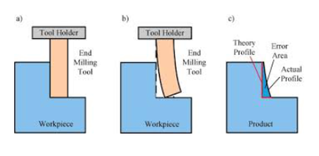 Over time, these side-load forces will bell-mouth the collet at its face. 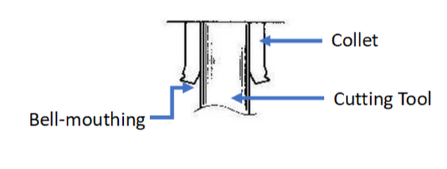 As the collet experiences bell-mouthing, the cutting tool is allowed to deflect more and more during milling operations. Unfortunately, the collet may still indicate good accuracy on a presetter where there are no side-load forces. However, once the tool is put into service and begins experiencing side-load forces, the cutting tool is allowed more room to deflect, resulting in increased chatter and reduced tool life. It is recommended to change collets out every 4-6 months, depending on usage, to ensure the most rigid and accurate collet chuck assembly. A good rule of thumb is to replace collets every 4-6 months to maximize the performance of your tooling. Again, collets are designed to wear out and are generally the least expensive component in the system. It is much less expensive to replace the collets as opposed to prematurely wearing out cutting tools. The following tips will help you in maintaining collets:
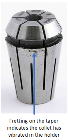
Signs that Your Collet Should be Replaced
If you see signs of fretting on the collet, it is advised to replace the collet. You should also ensure that collet nuts are tightened to the correct torque specifications during setup.
CLICK HERE to see all of our more in-depth articles on FRETTING to learn more. Technical Blog excerpt courtesy of Techniks USA Collets come in many different types and sizes. Here is an overview of three of the more popular types of collets, along with the pros and cons of each system. ER Collets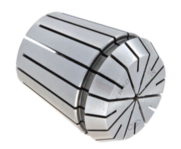 ER collets have between a 0.020” and 0.040” holding range The ER collet system has become very popular due to the flexibility of the system to hold a variety of cutting tool shank types including drills, end mills, and taps. Also, ER collets provide several solutions for increasingly popular coolant-through cutting tools. Most standard ER collets have between a 0.020” and 0.040” holding range, making them a good choice when needing to hold odd-sized cutting tool shanks. This holding range also means fewer ER collets are required to hold a range of cutting tool shank diameters as opposed to other collet systems like TG. The popularity of the ER collet system has led to several variations to hold a wide assortment of cutting tool shanks. Some ER collets have been modified with squares at the bottom to hold taps. Others have been modified to provide quick-change capabilities or compensation, also called “float”, for rigid tapping cycles as shown in the images below. Specialized ER ColletsOther modifications include special slotting designs that seal around the cutting tool shank and force coolant through channels in coolant-through tooling, as well as modifications to include coolant ports in the collet that direct coolant to the cutting area. TG Collets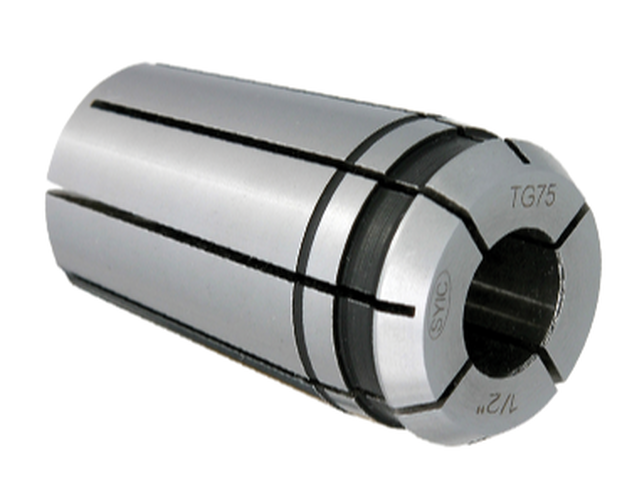 TG collets have about the same accuracy as DA collets, but because there are more slots, and therefore more faces clamping on the cutting tool shank, they tend to deliver greater holding power. TG can be a good solution for larger shank diameter cutting tools, but they generally limit how far down into a pocket you can reach due to interference with the collet nut, as TG collet nuts tend to be quite large. TG collets are not as popular as ER collets for several reasons. Most notably, the larger diameter collet nuts can require the use of extended end mills to avoid interference from the collet nut when milling pockets. Also, since TG collets have a very small collapse range, they are intended for use with one size cutting tool shank. ER collets, by contrast, offer a large collapse range that can be helpful when clamping odd-shank diameter tools. On the flip side, TG collets tend to have a bit more holding power than ER collets due to the collet base having a 4° taper as opposed to the 8° taper found in ER collets. This can make TG collets a good choice when machining with longer-length cutting tools. Double-Angle (DA) Collets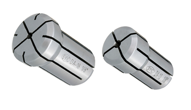 Please stop using DA collets in CNC Machining Double-Angle (DA) collets have been around for a long time and continue to be used in the market. There are, however, many issues associated with DA collets of which users should be aware.
Let's just clear the air and say it: Don't use them. If you have them in your shop, replace them with ER Collets and ER Collet Chucks as soon as possible and you will recoup the cost of the new holders and collets in your tool life probably within a month or two. One of the primary issues with DA collets is that they essentially clamp on the cutting tool shank with only two opposing faces in the I.D. bore. DA collets have four slots in the front of the collet and four slots in the back of the collet creating four clamping faces. However, when DA collets are tightened towards the lower end of their collapse range, two of the faces tend to be pushed out of the way so only two of the faces are clamping on the cutting tool shank. This may cause some runout at the nose when the tool is inspected in a presetter. Additionally, when the tool begins cutting and side forces are applied to the cutting tool, the cutting tool tends to deflect into the area where the faces are not clamping on the tool shank. This results in excessive chatter that dramatically reduces tool life and results in rough surface finishes. You will be hard-pressed to find a quality end mill holder manufacturer endorsing the performance of their tooling in DA collets. Edited by Bernard Martin 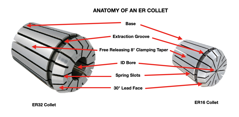 If you work in the metalcutting, signmaking or cabinet making manufacturing industry, the term “collets” is already very familiar to you. There are many types of collets used in many different industries and applications. This article is focused on collets used in rotary tool holders found in CNC milling machining centers and CNC Routers and also used in CNC Lathes and Swiss Style CNC's. Let's cover the basics: What are Collets?Collets are the critical connection between the cutting tool and the tool holder, also called a collet chuck. Most collets are round, cone-shaped, and slotted. Collets encircle the cutting tool shank to evenly distribute holding power around its center bore. Before getting too deep into the technical aspect of collets, It's going to be helpful to anyone new to the use of collets to understand the basic anatomy of collets and of a collet chuck system. How Collets Work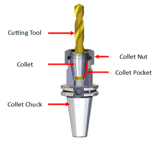 Collet ins depicted being held in a CAT 40 rotary collet chuck toolholder used in CNC milling machines. The tapered collet base is made to fit into the collet pocket of the collet chuck body. The free release locking tapered (16°included, 8° per side) design of the collet base and collet pocket allows the collet to be centered in the pocket as it is pushed in by the collet nut on the lead face during setup.
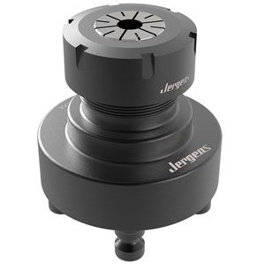
This centering effect enables the collet to achieve a high degree of accuracy (concentricity); much more than drill chucks and side-lock style end mill holders. As he collet nut is tightened down on the collet, it is pushed into the pocket collet chuck pocket. The slots in the collet allow the I.D. bore to collapse and apply clamping pressure to the cutting tool shank. It's essentially a spring that is compressed tight around the shank of the cutting tool such as a drill or end mill. The result is a very strong and rigid clamping force on the cutting tool. Since the collet base is tapered to match the collet pocket, tool runout (T.I.R.) is reduced. Total indicator runout (TIR) is a term often used in manufacturing, especially when dealing with rotating parts such as cutting tools, particularly endmills and drills. TIR is defined as the difference between the maximum and minimum values measured across an entire rotating surface about a reference axis. Jergen's 5-Axis ER Collet Fixtures Provide Simple Clamping of Cylindrical Parts in a CNC MIll4/12/2022 Looking for a simple and low profile solution for clamping cylindrical workpieces and round bars? Do you ever need to hold a round shank workpiece and machine it in a CNC Mill?
The ER Collet Fixtures provide a simple and low profile solution for clamping cylindrical workpieces using the same technology you are already familiar with in your rotary toolholders.
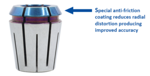
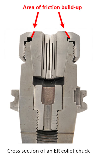
It’s been estimated that a tool with a run-out of 50% of the tool’s chip load will reduce its tool-life by 40%. That means that a 1/8” tool with a 0.00019” chip load per tooth will lose 40% of its tool-life with a run-out of less than 0.0001”. Excessive and inconsistent run-out from a properly setup ER collet chuck assembly typically occurs due to friction build-up between the 30° face of the collet and the collet nut.
 The result?
Other Parlec P3 collet advantages:
Don’t throw away you ER collet chucks to improve accuracy Try Parlec P3 collets and supercharge your ER collet system. Written and edited by Bernard Martin PowerCOAT Collet Nuts provide up to a 75% increase in holding power! 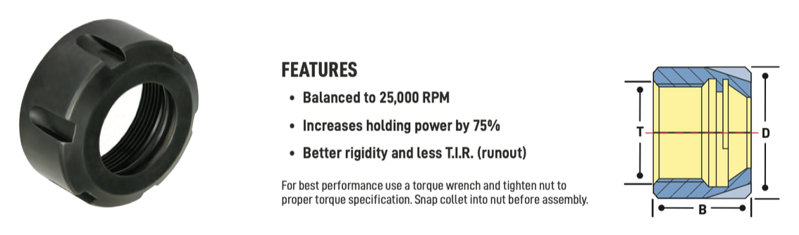 One of the most important elements of the toolholding 'system' is the collet nut. Each toolholder "system" consists of a precision ER tool holder that comes with a special "Power Coated" high power nut that holds tighter than any other nuts. According to Techniks, the 'Power Coat' nut is the secret to their high holding power. Because it holds so tight, the 'Power Coat' nut improves T.I.R., extends carbide tool life, and improves finish in heavy milling operations. Techniks recommends that for best results always tighten the nut to the proper torque using a torque wrench with a tightening stand, and never over-tighten the nut because this can damage both the collet and the collet pocket. To demonstrate the difference between an uncoated and coated collet nut, Mike Eneix, from Techniks did some testing. He took an uncoated, imported nut and put it to the test against the Parlec PowerCOAT nut. Mike took them to the limit to see which one gives you more holding power. Check out the video below! What makes the difference?As anyone knows who has changed a flat tire on their car, tightening down a nut on a 60 degree thread involves some friction as the mating metal surfaces interact. That's why nuts can be a bit 'hot' to the touch when you take them off. The objective with the "Power Coated" nuts was multifold:
First Techniks needed to reduce the coefficient of friction on the thread angle to enable more lubricity for the nut to tighten down farther. As we all know 'heat' causes metal to "grow" so what may at first appear to be tight, in fact, loosens, as soon as you stop tightening it. Second they needed to make sure that the front surface of the collet that engages the shorter 30 degree taper on the front of an ER collet did not 'twist' as the night tightened down. Both problems really involved reducing friction and through a combination of engineering tolerances and unique coating process we believe that we've found the most economical solution to eliminate the use of cheater bars and collet over torque. Here's what they've found out in testing the "Power Coated" Nuts:
“Power Coat” is an innovative, permanent coating that increases clamping pressure of the nut up to 75% compared to standard ER nuts. More holding power reduces the chance of spinning the shank of the tool inside the collet, which can cause premature failure of the collet. It’s time for machine tool builders and machining companies to shelf the long-standing ISO 1940-1 standard in favor of ISO 16084:2017. Not only is balancing tools rarely necessary, it can also be risky. A lot of conflicting information has circulated over the years about balancing tools. As an author of the new standard for calculating permissible static and dynamic residual unbalances of rotating single tools and tool systems – ISO 16084:2017 – allow me to clear some things up and, hopefully, make life a little easier for you.
Since its institution in 1940, the G2.5 balance specification has been widely accepted across the industry; i.e., “it’s how things have always been done.” However, machines were much slower 80 years ago. Back then, the most advanced machines would have spun larger, heavier tools at a maximum speed of about 4,000 RPM. If you applied the math from those days to today, you’d get unachievable values. For example, the tolerances defined by G2.5 for tools with a mass of less than 1 pound rated for 40,000 RPM calculates to 0.2 gram millimeters (gm.mm.) of permissible unbalance and eccentricity of 0.6 micron. This isn’t within the repeatable range for any balance machine on the market. Similarly, application-specific assemblies, for operations like back boring and small, lightweight, high-speed toolholders, can’t be accurately balanced for G2.5. Machine tool builders rely on an outdated number, too, often basing spindle warranty coverage on using balanced tools at very specific close tolerances. While it’s true that poorly balanced tools run at high speeds wear a spindle faster, decently balanced tools performing common operations won’t wear spindles or tools drastically and deliver the results you’re looking for. While it’s true that poorly balanced tools run at high speeds wear a spindle faster, decently balanced tools performing common operations won’t wear spindles or tools drastically and deliver the results you’re looking for. A Little Lesson About ForcesThis all begs the question: When do you need to take the time to balance holders? I would argue that tools require balancing only if they’re notably asymmetrical or being used for high-speed fine finishing. Here’s a rule I’ve long followed: If cutting forces exceed centrifugal forces due to unbalance, high-precision balancing isn’t needed because the force required to balance the tool will most likely be less than cutting forces.
At that point, aggressive cutting – not unbalance – is going to damage the spindle. Unbalanced tools are also blamed for issues that turn out to be misunderstandings about a machine’s spindle. I’ve visited shops with new high-speed spindles that had trouble running micro tools over 15,000 RPM. They rebalanced all the tools on the advice of their machine tool supplier, but to no avail. It turned out the machine was tuned for higher torque and higher cutting forces. Before going to the effort of balancing toolholders, work with your machine builder to understand where a spindle is tuned. Not only is balancing tools rarely necessary, it can also be risky. Our inherently asymmetrical fine-boring heads are a good example. Because we balance them at the center, a neutral position of the work range, you lose that balance if you adjust out or in. To adjust, you’d typically add weight to the light side, which can be a problem for chip evacuation and an obstructor. Or you can remove weight from the heavy side, but that means you have to put some big cuts on the same axis of the insert and insert holder, ultimately weakening the tool. In longer tool assemblies, common corrections made for static unbalance can also cause issues. It happens when a toolholder is corrected for static unbalance in the wrong plane; i.e., adding or removing weight somewhere on the assembly that’s not 180 degrees across from the area where there’s a surplus or deficit. Once the tool is spun at full speed, those weights pull in opposite directions and create a couple unbalance that often worsens the situation.  All the components of Big Kaiser's Mega ER Grip Series - Body, Collet and Collet nut - Are all balanced for high speed machining A Cautionary TaleIf you do go down the balancing road, you’d better know where you can modify tools, what’s inside, how deep you can go, and at what angles. Whether you’re adding or removing material on a holder, I highly recommend consulting the tool manufacturer for guidance first. As a cautionary tale, consider a customer who was attempting to balance a batch of our coolant-fed holders. Based on the balancing machine, the operator drilled ¼-inch holes at the prescribed angle into the body of the holders. Not realizing what was inside, he drilled into cross holes connecting coolant flow and ruined several holders. Tooling manufacturers are doing their part to avert disasters like this. For most, simple tools like collet chucks or hydraulic chucks are fairly easy to balance during manufacturing. We account for any asymmetrical features while machining and grinding holders and pilot each moving part, ensuring they’ll locate concentrically during assembly. These measures ensure the residual unbalance of the assemblies is very, very low and eliminate the need for balancing.
Decades of the same standards have conditioned us to think a certain way about balancing tools. While it seems logical that every tool must be balanced, it’s just not the case: Many issues attributed to unbalance aren’t caused by unbalance, and the risks of balancing every single tool often aren’t worth the reward.
Save your balancing time and resources for high-speed fine finishing. If you do have work where balance is crucial, consider how the tools you buy are balanced and piloted out of the box and/or consult your partners before making any modifications. |
Technical Support BlogAt Next Generation Tool we often run into many of the same technical questions from different customers. This section should answer many of your most common questions.
We set up this special blog for the most commonly asked questions and machinist data tables for your easy reference. If you've got a question that's not answered here, then just send us a quick note via email or reach one of us on our CONTACTS page here on the website. AuthorshipOur technical section is written by several different people. Sometimes, it's from our team here at Next Generation Tooling & at other times it's by one of the innovative manufacturer's we represent in California and Nevada. Archives
July 2024
Categories
All
|
 RSS Feed

About
|
© 2024 Next Generation Tooling, LLC.
All Rights Reserved Created by Rapid Production Marketing
|
