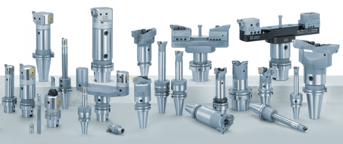
 Put simply, the manufacturing process of boring is enlarging a hole in a piece of metal. There are quite a few different pieces of machinery or approaches that can be used to make holes from lathes and mills to line boring or interpolation. We wanted to do a quick break down of the different kinds of boring tools available to bore holes and/or secondary boring operations. Boring BarsBoring deep holes can involve extreme length-to-diameter ratios, or overhang, when it comes to tooling assemblies. Since it can be difficult to maintain accuracy and stability in these scenarios, we need boring bars to extend tooling assemblies and while maintaining the rigidity to make perfect circles with on-spec finishes. Solid boring bars Typically made of carbide for finishing or heavy metal for roughing, solid boring bars have dense structures that make for a more stable cut as axial force is applied. Damping bars When cutting speeds are compromised, or surface finishes show chatter in a long-reach boring operation, damping bars are an option. They have integrated damping systems. Our version, the Smart Damper, works as both a counter damper and friction damper so that chatter is essentially absorbed. 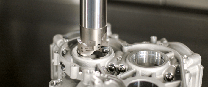 Boring HeadsBoring heads are specifically designed to enlarge an existing hole. They hold cutters in position so they can rotate and gradually remove material until the hole is at the desired diameter. Rough boring heads Once a bore is started with a drill or by another method, rough boring heads are the choice for removing larger amounts of material. They are built more rigid, to handle the increased depths of cut, torque and axial forces needed to efficiently and consistently make the passes to remove materials. Fine boring heads Fine boring heads are best used for more delicate and precise removal of material that finishes the work the rough boring head started. They are often balanced for high-speed cutting since that’s the best approach for reaching exact specifications. Twin cutter boring heads Most boring heads feature one cutter that cuts as its feed diameter is adjusted by the machine. There are twin cutter boring heads that can speed up cutting and add versatility. For example, the Series 319 and other BIG KAISER twin cutter boring heads include two cutters that can perform balanced or stepped cutting without additional accessories or adjustments by switching the mounting locations of the insert holders that have varied heights. Digital boring heads Traditionally, adjusting boring heads has been painstaking and time-consuming, especially when it’s done in the machine. It’s easy to make mistakes when maneuvering to read the diameter dial and adjusting it to the right diameter. Digital boring heads have a LED that makes precise adjustments much easier. 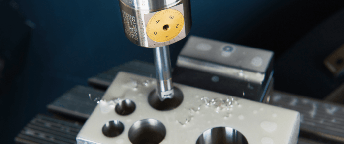 Starter DrillsSince cutters are on diameter of boring heads and not their face, they are not able to initiate a hole on a flat surface or raw material. Especially in smaller bores, fluted drills called starter drills can be used to get the hole started before rough boring.
Specialty boring heads Back boring and face grooving heads, as well as chamfering insert holders, are available for some of the most common secondary operations, after a hole is bored. We produce specific heads with cutters at the appropriate angles so each of these operations can be done without manually moving the part, changing the tool or adjusting the cutter angle. Modular boring tools Since limiting length-to-diameter ratios is so crucial to boring success, it’s extremely valuable to be able to make your tooling assembly as short as possible. Our modular components are based on a cylindrical connection with radial locking screw that allows for the ideal combination of different kinds of shanks, reductions and extensions, bars, ER collet adapters and coolant inducers. Looking for some help finding the right boring equipment for your next job or new machine? Our engineers are here to help. Get in touch with us here.
0 Comments
It’s time for machine tool builders and machining companies to shelf the long-standing ISO 1940-1 standard in favor of ISO 16084:2017. Not only is balancing tools rarely necessary, it can also be risky. A lot of conflicting information has circulated over the years about balancing tools. As an author of the new standard for calculating permissible static and dynamic residual unbalances of rotating single tools and tool systems – ISO 16084:2017 – allow me to clear some things up and, hopefully, make life a little easier for you.
Since its institution in 1940, the G2.5 balance specification has been widely accepted across the industry; i.e., “it’s how things have always been done.” However, machines were much slower 80 years ago. Back then, the most advanced machines would have spun larger, heavier tools at a maximum speed of about 4,000 RPM. If you applied the math from those days to today, you’d get unachievable values. For example, the tolerances defined by G2.5 for tools with a mass of less than 1 pound rated for 40,000 RPM calculates to 0.2 gram millimeters (gm.mm.) of permissible unbalance and eccentricity of 0.6 micron. This isn’t within the repeatable range for any balance machine on the market. Similarly, application-specific assemblies, for operations like back boring and small, lightweight, high-speed toolholders, can’t be accurately balanced for G2.5. Machine tool builders rely on an outdated number, too, often basing spindle warranty coverage on using balanced tools at very specific close tolerances. While it’s true that poorly balanced tools run at high speeds wear a spindle faster, decently balanced tools performing common operations won’t wear spindles or tools drastically and deliver the results you’re looking for. While it’s true that poorly balanced tools run at high speeds wear a spindle faster, decently balanced tools performing common operations won’t wear spindles or tools drastically and deliver the results you’re looking for. A Little Lesson About ForcesThis all begs the question: When do you need to take the time to balance holders? I would argue that tools require balancing only if they’re notably asymmetrical or being used for high-speed fine finishing. Here’s a rule I’ve long followed: If cutting forces exceed centrifugal forces due to unbalance, high-precision balancing isn’t needed because the force required to balance the tool will most likely be less than cutting forces.
At that point, aggressive cutting – not unbalance – is going to damage the spindle. Unbalanced tools are also blamed for issues that turn out to be misunderstandings about a machine’s spindle. I’ve visited shops with new high-speed spindles that had trouble running micro tools over 15,000 RPM. They rebalanced all the tools on the advice of their machine tool supplier, but to no avail. It turned out the machine was tuned for higher torque and higher cutting forces. Before going to the effort of balancing toolholders, work with your machine builder to understand where a spindle is tuned. Not only is balancing tools rarely necessary, it can also be risky. Our inherently asymmetrical fine-boring heads are a good example. Because we balance them at the center, a neutral position of the work range, you lose that balance if you adjust out or in. To adjust, you’d typically add weight to the light side, which can be a problem for chip evacuation and an obstructor. Or you can remove weight from the heavy side, but that means you have to put some big cuts on the same axis of the insert and insert holder, ultimately weakening the tool. In longer tool assemblies, common corrections made for static unbalance can also cause issues. It happens when a toolholder is corrected for static unbalance in the wrong plane; i.e., adding or removing weight somewhere on the assembly that’s not 180 degrees across from the area where there’s a surplus or deficit. Once the tool is spun at full speed, those weights pull in opposite directions and create a couple unbalance that often worsens the situation. 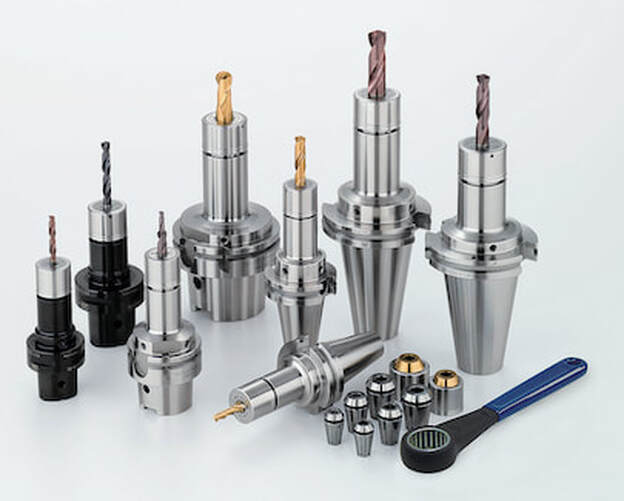 All the components of Big Kaiser's Mega ER Grip Series - Body, Collet and Collet nut - Are all balanced for high speed machining A Cautionary TaleIf you do go down the balancing road, you’d better know where you can modify tools, what’s inside, how deep you can go, and at what angles. Whether you’re adding or removing material on a holder, I highly recommend consulting the tool manufacturer for guidance first. As a cautionary tale, consider a customer who was attempting to balance a batch of our coolant-fed holders. Based on the balancing machine, the operator drilled ¼-inch holes at the prescribed angle into the body of the holders. Not realizing what was inside, he drilled into cross holes connecting coolant flow and ruined several holders. Tooling manufacturers are doing their part to avert disasters like this. For most, simple tools like collet chucks or hydraulic chucks are fairly easy to balance during manufacturing. We account for any asymmetrical features while machining and grinding holders and pilot each moving part, ensuring they’ll locate concentrically during assembly. These measures ensure the residual unbalance of the assemblies is very, very low and eliminate the need for balancing.
Decades of the same standards have conditioned us to think a certain way about balancing tools. While it seems logical that every tool must be balanced, it’s just not the case: Many issues attributed to unbalance aren’t caused by unbalance, and the risks of balancing every single tool often aren’t worth the reward.
Save your balancing time and resources for high-speed fine finishing. If you do have work where balance is crucial, consider how the tools you buy are balanced and piloted out of the box and/or consult your partners before making any modifications. A guest blog from BIG KAISER. 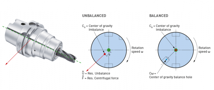 High-speed machining started getting popular in the ‘90s, especially in aerospace where they replaced fabricating processes with machining monolithic parts like wing struts from billets. Machine tools capable of spinning cutting tools at tens of thousands of RPM made it easier to produce these parts quickly. Like machines, holders adapted. The centrifugal forces they had to manage in order to keep tools cutting correctly became extreme. The toolholding systems available at that time were found not to be as effective as the shallower 1-to-10 taper ratio of the German hollow taper shank, hohl shaft kegel (HSK) in German. The HSK has since been standardized to ISO specifications (12164-1, -2). HSK is now available in several sizes and forms to fit with small to large machines. For the most part, the market has settled on the form A for general milling. It has been adopted in Japan, North America and Europe and is truly one of the only worldwide-side toolholder standards. Form E or F is for high-speed machining. The forms have different features depending on the standard they follow. In the end, to achieve efficient tool life, proper finish and productivity in high-speed work, holders need to be as rigid, compact and short as possible to keep the whole assembly stable. What to know when choosing a high-speed tool holder
When it comes to balancing holders, the quality G2.5 is widely used in the industry and is described in the ISO 1940-1 (issued in 2003) standard. However, this quality class is often over-specified and is in many cases not economically or technically feasible, especially when applied to smaller and lighter tools. Standards often applied to tools are more suited for rigid rotors and are practical in a broader use for balancing.
However, it cannot be applied to a complete system of spindles, tool holders and tools adequately and within technical constraints. For example, a tool to be compliant will have to be balanced to less than 1 gmm/kg at a speed of 25,000 rpm, which in turn corresponds to a mass eccentricity of less than 1 μm. This allowable tolerance is less than the interchange accuracy for even HSK, essentially negating all the costs and time for balancing the tool to such a strict tolerance. For this reason, all BIG KAISER tool holders are balanced according ISO 16084 (issued in 2017) specifically developed for rotating tool systems. ISO 16084 focuses on the interaction between spindle and tool factoring in the allowable load on the spindle bearings generated by the tool’s imbalance. This load must not exceed one percent of the dynamic load capacity of the spindle bearings. According to ISO 16084, the allowable unbalance tolerance is specified in [gmm] and is not expressed using a special quality grade [G]. In conclusion, BIG KAISER does not indicate any G-values for balancing quality, but rather the maximum rotational speeds of the individual tool holder. The BIG Kiaser MEGA holder program includes a variety of styles that can be used up to 40,000 RPM. They guarantee 100 percent concentricity and runout accuracy down to .00004" at the nose. They are built specifically to withstand speed and forces required in today’s high-throughput environment. For more information on BIG KAISER's approach to balancing tool holders, click here. To learn more about our high-performance tool holders here. We are very excited to announce that we are now able to offer on-site technical training to YOUR machinists at YOUR location! This is offered at no charge to customers who use any of the manufacturer's whom we represent in California and Nevada. However, just because you don't purchase things from us, don't feel left out! We also offer on-site topic specter training on any of the following topics for $150/hour. Each presentation lasts about 2 hours. The presentations last approximately 45-60 minutes with the remaining time for Q&A and discussion about unique applications in your facility.  Training Classes Available: Machining 101
Advanced Part Manufacturing:
Our most widely used finish boring system, BIG KAISER Series 112, features a high precision boring head with a center-mount boring bar or boring bar/insert holder combo with a predefined fixed offset designed to bore one specific size. Although the BIG KAISER system provides a multitude of standard components to create the ideal combination of boring bar and insert holder – you may not always have the ideal combination at your disposal. Don’t fret – that is the beauty of the system. 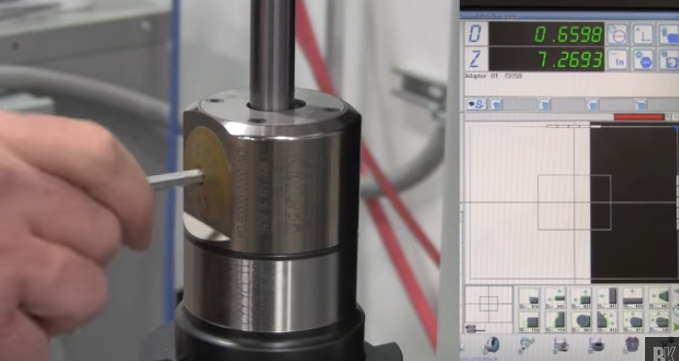 The total boring range of your assembly is reached through radial adjustment of the bar. However, when doing so, there is still always the consideration of balance while assembling the tool. As logic would tell you, the farther away from the boring head’s centerline you offset the boring bar, the greater the unbalance. This affects not only the performance of the tool, but more importantly, the results. And this is especially true for deep hole boring. To get the greatest productivity and flexibility from the BIG KAISER 112 boring system, we recommend replacing the fixed bar & insert holder with a radial adjustment bar & insert holder which keeps the bar at centerline at all times. This allows for different boring ranges to be reached, all while keeping the tool as balanced as possible. In this video, Matt Tegelman, Applications Manager and BIG KAISER Product Manager, walks you through the process of adjusting the fixed boring bars and inserts holders. And if balance is a concern, utilizing the radial adjustable option, Matt demonstrates how to properly center the boring bar on both a tool presetter and in a machine spindle, and finally, how to fine-adjust to the desired diameter. Watch for more of these brief instructional reference videos here on Cut to the Chase blog in the near future.
Tags: balance, boring tool, deep hole boring, How-To, KAISER, Matt Tegelman, tool presetter by Bernard Martin We often run end mill "tests" to determine which tool performs best. Obviously, our goal is to "win' the test and get more business for our manufacturer's. This is article is about one our "tricks" and it's also why we represent both cutting tool manufacturers and rotary tool manufacturers. We want to make sure that the products work together.  As a general rule most cutting tool & tolholder manufacturers prefer to use single angle (ER/DR style) collet chucks for general purpose cutting tool applications under 1/2" (12mm). The rules are a bit different in High Speed Machining, as there are many more things to consider, but the problems of TIR at high speeds, where you can hear and feel the chatter, are still there in general end mill cutting operations at lower RPM. It's all boils down to runout and uneven chip load. 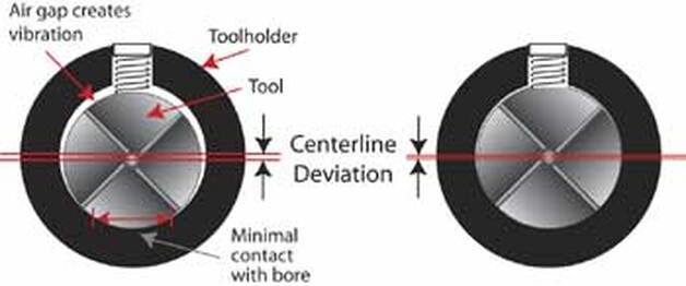
|
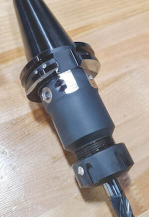
The mouth of the machining center spindle can grow and eventually "bell mouth" with these older style steep taper holders. As it grows the BT and CAT tool is under constant drawbar pull, is pulled up deeper inside the expanded spindle taper. This causes the Z-axis offset to change and can lead the toolholder getting stuck in the spindle.
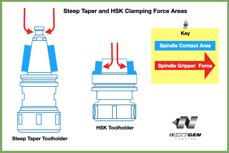
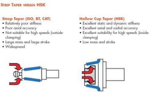
Major Differences between Steep Taper and HSK
- Taper: NMTB, BT and CAT-V holders typically use a 7:24 taper while HSK uses a shallow 1:10 taper
- Dual Contact: NMTB, CAT and BT only have taper contact with the spindle while HSK is designed for both Taper and Flange contact the spindle
- Drawbar: CAT and BT holders are held into the spindle by draw bar fingers that wrap around the outsideof the retention knob (pull stud) while with HSK the drawbar fingers are inside the hollow shank.
Dual Contact
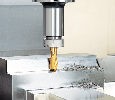
A standard steep V-taper tool system is designed to make contact along a fixed taper in the machining center spindle. The tool is held firm against this taper by the drawbar inside the spindle of your CNC. When a conventional holder is seated in the CNC spindle, there is approximately a 3 mm gap between the tool holder flange and the spindle face.
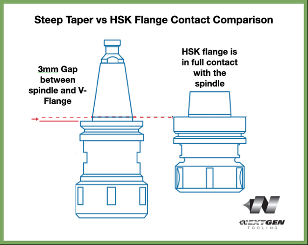
Cutting tools generally takes higher radial forces because the flange contact and taper contact combine to resist deflection.
Drawbar
Technical Support Blog
We set up this special blog for the most commonly asked questions and machinist data tables for your easy reference.
If you've got a question that's not answered here, then just send us a quick note via email or reach one of us on our CONTACTS page here on the website.
Authorship
Our technical section is written by several different people. Sometimes, it's from our team here at Next Generation Tooling & at other times it's by one of the innovative manufacturer's we represent in California and Nevada.
Archives
July 2024
June 2024
May 2024
April 2024
March 2024
February 2024
January 2024
December 2023
November 2023
October 2023
September 2023
August 2023
July 2023
June 2023
May 2023
April 2023
March 2023
February 2023
January 2023
December 2022
November 2022
October 2022
September 2022
August 2022
July 2022
June 2022
May 2022
April 2022
March 2022
February 2022
December 2021
November 2021
October 2021
September 2021
August 2021
July 2021
June 2021
May 2021
April 2021
March 2021
February 2021
January 2021
December 2020
November 2020
October 2020
September 2020
August 2020
July 2020
June 2020
May 2020
March 2020
February 2020
January 2020
September 2019
August 2019
July 2019
June 2019
May 2019
March 2019
January 2019
September 2018
June 2018
April 2018
February 2018
December 2017
November 2017
October 2017
August 2017
June 2017
April 2017
March 2017
February 2017
January 2017
December 2016
November 2016
October 2016
August 2016
March 2016
February 2016
January 2016
November 2015
August 2015
July 2015
May 2015
April 2015
March 2015
November 2014
August 2014
July 2014
December 2013
November 2013
September 2013
July 2013
March 2013
December 2012
March 2012
November 2011
May 2011
March 2011
January 2011
December 2010
November 2010
October 2010
Categories
All
5th Axis
Aerospace
Allied Machine
Aluminum Oxide
Angle Head
AT3
Balance
Bellmouthed Hole
Big Daishowa
Big EWA Automatic Boring
Big Kaiser
BIG Plus
Blue Photon
Bone Screws
Boring Tool
Carbide
Carmex Precision
CBN
Centerline Deviation
Ceramic Black
Ceramic End Mill
Ceramic Inserts
Ceramic Oxide
Ceramic Whiskered
Ceramic White
Chamfer
Champion Tool Storage
Chip Breaking
Circular Saw
Class Of Fit
CNC Lathe Tooling
Collet
Collet Chuck
Collet ER
Collet TG
Composites
Covid-19
Deep Hole Boring
Deep Hole Drilling
Drilling
Dual Contact
Dyna Contact Gage
Dyna Force Tool
Dyna Test Bar
EMO
End Mill
Exotap
Facemill
Fixturing
Fretting
Gaylee Saw
Hard Turning
Heimatec
Helical Interpolation
Hohl Shaft Kegel
How Its Made
HSK A
HSK-A
HSK E
HSK-E
HSK F
HSK-F
HXL Tap
Hy Pro Tap
Hy-Pro Tap
IMTS
Jergens
Jergens OK-Vise
Kurt
Lang
Live Tooling
MA Ford
Maintenance Cart
Mapal
Martindale Saw
Material: Aluminum
Material: CFRP
Material: D2
Material: Hastelloy
Material: Inconel
Material: Peek
Material: Stone
Material Titanium
Material: VC 10
Material: VC-10
Metric Course Thread
Metric Fine Thread
Metric Thread Chart
Microconic
Micromachining
ModLoc
Modular
Mogul Bars
MPower
NextGen Tooling
No Go Too Loose
NTK
NTK HX5
On Site Training
OptiMill-SPM
OSG Tap & Die
Oversized Thread
Parlec
PCD
PCT Firm Hold
Platinum Tooling
Projection Length
Pull Studs
Reamer
Retention Knob
Rotary Toolholders
Rotary Toolholders BT
Rotary Toolholders CAT
Rotary Toolholders HSK
Rotary Toolholders Hydraulic
Rotary Toolholders Shrink
Rough Thread
Runout
Runout Axial
Runout Radial
Safe-Flex
Saw Selection
Short Tap Life
Sialons
Silicon Nitride
Smart Damper
Speed Increaser
SpeedLoc
Speroni STP Essntia
Spindle Mouth Wear
Surface Roughness Ra
Surface Roughness RMS
Swiss
Swiss Machining
Taper Wear
Tapping Feed
Tapping; Form
Tapping IPM
Tapping: Roll
Tapping RPM
Tapping Speed
Tap Tolerance
Technical Training
Technicrafts
Techniks USA
Thread Milling
Thread Whirling
T.I.R.
Tolerance
Toolchanger Alignment
Toolholder Taper
Tool Presetter
Torn Thread
Troubleshooting
UNC Thread Size
Undersized Thread
UNF Thread Size
Unilock
Vises
Washdown Tool
Workholding
 RSS Feed

About
|
© 2024 Next Generation Tooling, LLC.
All Rights Reserved Created by Rapid Production Marketing
|
