|
We are very excited to announce that we are now able to offer on-site technical training to YOUR machinists at YOUR location! This is offered at no charge to customers who use any of the manufacturer's whom we represent in California and Nevada. However, just because you don't purchase things from us, don't feel left out! We also offer on-site topic specter training on any of the following topics for $150/hour. Each presentation lasts about 2 hours. The presentations last approximately 45-60 minutes with the remaining time for Q&A and discussion about unique applications in your facility.  Training Classes Available: Machining 101
Advanced Part Manufacturing:
3 Comments
Next Generation Tooling is excited to offer some new services coming in 2015! Below is a very fast video of our new training series on Tapping which we can present to your manufacturing team at your site. It's a comprehensive overview of screw thread terminology, thread forms, fundamentals of threads, classes of fit, Tap basics, types of chamfers, the tapping process,tap types, screw thread inserts, helix angles, core diameters, re an hook angles, thread reliefs, pitch tolerances, H limits, Tap substrates, Surface treatment and coatings, tapping speeds, tap drill sizes.
written by, Dave Nelson, edited by Bernard Martin  Understanding tool geometry and selecting the right tap for different workpiece materials can help take the anxiety out of tapping operations. Many machinists have learned to dread tapping. The story goes something like this. They press cycle start and then step back because the machine is now in control. If the tap should hit bottom, too bad; the cycle must be completed—no feed-hold allowed here. If the wrong feed rate was programmed, tough luck; the feed rate override is disabled. What else is there to do but cringe as the tap enters the hole? That’s one of the reasons tapping causes anxiety among CNC machine operators. That anxiety leads operators to take too many precautions to assure the tap will complete its job of cutting an internal thread. Other factors can fuel tapping anxiety. Feed rates are typically much higher than for most other cutting tools. With each revolution of the tap, the tool needs to advance one thread pitch. As an example, a 5⁄16-18 tap feeds at 1 divided by 18, or 0.055 IPR. The 0.257-dia. drill that created the hole might feed closer to 0.005 IPR It is quite common to tap at slower speeds to “feel” more in control. Slowing the spindle speed is the only way to effectively slow the feed into the hole. A 5⁄16-18 tap cutting at a spindle speed of 900 rpm would feed at 50 IPM, but at 720 RPM the feed would be only 40 IPM. Understanding Tap Geometry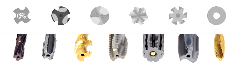 However, while tapping can be tricky, it is not beyond understanding. Tapping problems can be simplified and reduced by understanding tool geometry and what taps are best suited for a given application. Lowering the chip load can eliminate premature wear on a tap. Defined as the load induced on any one cutting edge, chip load is typically controlled by altering the feed rate. As mentioned earlier, this is not possible when tapping but the chip load can be altered through tap selection. One approach might be to use taps with more flutes. With every flute added to the tap, a cutting face is added. With more cutting faces, the load on each tooth is reduced. For example, a 4-flute tap would have half the chip load per tooth of a 2-flute tap. This jives with standard metalcutting advice, which is to always use a maximum number of flutes. However, for tapping this advice would probably be wrong. “More flutes means there is less space for chips as they are cut,” said David Miskinis, senior application specialist, holemaking for Kennametal Inc., Latrobe, Pa. “More flutes on the same circumference means smaller flutes, both in width and depth. With smaller space comes the risk of packing chips, which can lead to broken taps.” “Basically, a longer chamfer length means longer tool life,” said Dr. Peter Haenle, president of Guhring Inc., Brookfield, Wis. “The load during the cutting process is distributed over a longer cutting edge with a lower chip load.” There are three common lengths of tap chamfers: taper at 7-10 threads, plug at three to five threads and bottoming with one to two threads. To provide more options, tap manufacturers have added a few more forms, including a form consisting of a two- to three-thread length, sometimes called semibottoming. Adding length to the chamfer distributes the chip load over a longer cutting face. Effectively, more teeth are cutting the thread, similar to a single-point threading tool taking multiple passes. “Chamfer lengths have a huge impact on tap life because they affect chip load,” Miskinis explained. “When comparing chamfer lengths of four threads or fewer, the tool life will double for every half thread added to the length.” Clearly, increasing chamfer length in taps is desirable. Shorter chamfer lengths, such as in bottoming taps, wear faster and should be avoided, if possible. Unfortunately, there may not always be a choice. “Taps with smaller chamfer lengths are usually used to keep the difference between hole depth and thread length to a minimum,” Haenle said. “Very often, the design of the part forces the use of taps with short chamfer lengths.” Another way to tap more effectively is to manage chip thickness. For example, it is possible to thin the chip too much when tapping. Stringy chips can result from using taper chamfers and the tap may create a bird’s nest of chips, preventing lubricant from reaching the tool and chips from properly evacuating. As in other types of machining operations, increasing chip load can help break the chips. Tap breakage is another issue that creates anxiety among machinists. The saying goes that it’s not the fall that kills you, it’s the sudden stop. But in tapping, it’s not the sudden reversal that causes taps to break, it’s the chips clogging the tool flutes. In some cases, this means chips are packed so tightly so that newly formed chips simply have no place to go, and the tap breaks from the stress. Selecting a TapBecause tapping is a relatively complex operation, and because there are so many taps to choose from, selecting a tap can seem a daunting task. The main reason there are so many taps is because there are so many work materials. Tap manufacturers tailor tap design to the work material primarily through rake and relief. The cutting face is that portion of the tap flute located between the major and minor diameter of the thread that cuts, or shears, the workpiece. The rake is the angle of the cutting face compared to a line from the center of the tap to the cutting face at the major diameter. 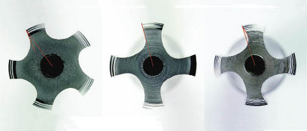 The image at left is of a tap with negative rake resulting in a strong cutting face for tough materials. Note that the cutting face at the root of the thread leads the remainder of the cutting edge. The center image shows a neutral rake. Here a line drawn along the cutting face continues to the center of the tool. The image at right is of a tap with a positive rake for free cutting of softer materials. Note how the cutting face leads from the major diameter, the reverse of the negative rake. A rake is positive if the crest of the cutting edge is angularly ahead of the remaining part of the face. While not as strong as negative rakes, positive rake angles have excellent shearing capabilities. A negative rake has the crest of the cutting face behind the rest of the cutting face. While this is a stronger geometry than a positive rake, it also requires more torque and creates more heat in the cut. The shape of the cutting face is also a factor in tap performance. Cutting faces can also be straight or curved. The straight surfaces are normally referred to as rakes or straight rakes and the curved surfaces as hooks. “Applying a rake, or straight face, will improve strength while a hook, or curved shape, will result in greater shearing ability,” said Andrew Strauchen, engineering and marketing manager, OSG Tap & Die Inc., Glendale Heights, Ill. “For performance taps, cutting [rake] angles are determined by the intended work material; higher angles are used for softer materials and low angles for harder materials.” Tap relief is defined as the removal of metal from behind the cutting edge. A higher relief indicates more clearance between the tool and the workpiece. There are three main types of relief: concentric, eccentric and con-eccentric. Concentric relief indicates that the lands of the tap, the part of the tap that remains after the flutes are cut, are concentric with the threads. This actually provides no relief and thus the surface of the tap rubs on the surface of the threads being cut. Hand taps are made with concentric relief. Because they are used by hand, cutting speeds are low and friction and heat do not limit tool life. Because the lands are concentric, the threads on the tap help guide the tool into the threads on the workpiece as they are cut. Eccentric relief means that the lands are cut to an arc that is not on center with the bulk of the tool. This type of relief provides the best clearance between the tap and the thread being cut. Because the tool doesn’t rub against the material, friction can be minimized. Con-eccentric relief is a combination of the other two styles. A small part of the land remains concentric at the leading edge while the rest of the relief is eccentric. This style provides a balance between reduced friction, as provided by eccentric relief, and tool guidance, as provided by concentric relief. Concentric relief and, to a lesser degree, con-eccentric relief taps rub the workpiece material as the tool enters and exits the hole, causing friction, which in turn produces heat. Heat diminishes tool life. As a result, premium taps are most often made with eccentric relief. “The higher the relief, the lower the friction of the tool,” Haenle said. “Therefore, a higher relief results in less wear and longer tool life. However, a lower relief guides the tool better in the axial direction because it has less tendency to cut in the radial direction.” Premium taps are not for all machines. A high-end tap will not guide itself when creating the thread. Therefore, taps with eccentric relief require the machine’s feeding mechanism to be highly accurate. “In newer CNC machines, you can use taps with higher relief angles,” Haenle said. “On the other hand, when using older equipment or drilling machines with less rigidity and with standard tapping chucks, a smaller relief angle helps to guide the tap better.” Tap manufacturers understand the balance between edge strength and the cutting edge’s ability to shear the workpiece.
To develop the proper geometry for a given application, tap designs can be complex. OSG has designed taps for vertical and horizontal machining: the Hypro HXL for horizontal and VXL for vertical. “We coupled a higher rake with a higher spiral to produce longer chips, which is necessary for chip evacuation in deep-hole vertical applications,” Strauchen explained. “With a unique flute form, we are able to create a tightly bound chip that peels away from the tap and holder when exiting the hole.” Horizontal machining, which can use gravity as an advantage, requires different geometries than vertical machining, he continued. “We lowered the rake angle and slowed the helix to induce a short, broken chip easily flushed out in horizontal applications. This design not only eliminates the bird nesting issue, but also extends tool life.” For any questions about your specific tapping problems be sure to contact us or set up an appointment to solve your tapping problems. February 2023 editors note: Images, graphics and copy have been edited since original publication date.
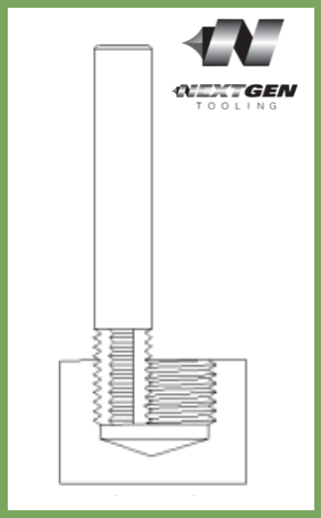
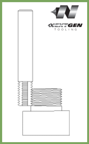
via OSG Tap & Die Jan 2, 2023 editors note: This article has been updated with new drawings and videos since it's original publication date. 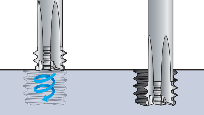 The machining technique for OSG’s thread mills have been developed for thread milling on a 3-Axis, 4-Axis and 5-Axis CNC controlled machine tool. The thread is processed by advancing one pitch feed per revolution in the axial direction, utilizing the planet-like rotation and revolution movements of the tool. Internal and external thread, right or left hand threads can all be produced with this one tool, simply by changing the direction of rotation and/or feed. This process is called Helical Interpolation and will be explained in greater detail below. Threading Process
The transition between the start and the finish of the milling operation must be smooth, and the appropriate amount of feed is essential for minimizing milling resistance. There are many different methods for using this tool, but our research has shown that this technique provides the most precise and efficient operation. 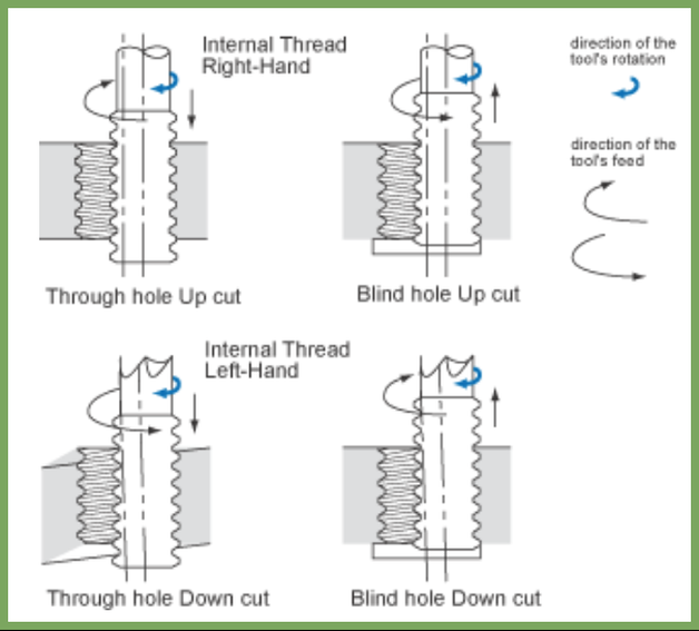 Understanding Thread Mills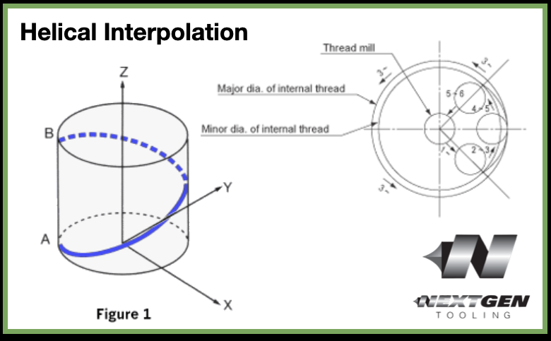 Figure 1. Helical Interpolation Any three axis mill that is capable of helical interpolation can be used for thread milling. Helical interpolation involves three axes moving simultaneously. Two axes, 'X' and 'Y', move in a circular motion while the 'Z' axis moves in a linear motion. For example, the path from point A to point B (Figure 1) on the periphery of the cylinder combines a circular movement in the 'X-Y' plane with linear movement along the 'Z' axis. The 'X' and 'Y' circular motion will determine the diameter of the thread. The 'Z' axis linear motion will cut the pitch (or lead) of the thread.
All of the straight flute thread mills are for internal threads only. All of the staggered tooth thread mills will cut both the internal and external threads. The helical thread mills over 0.187 diameter will also cut both internal and external threads. Staggered tooth thread mills have every other tooth removed in a staggered pattern; as the tool rotates the adjacent flute fills in for the tooth that was removed. This helps to reduce side cutting pressure, thus reducing chatter. This can be extremely beneficial in small external sizes and for set-ups that lack rigidity. Helical fluted thread mills are also designed to reduce side cutting pressure by distributing the cutting pressure along a helical flute. Although these tools cost slightly more, their high performance design allows for less chatter and higher feed rates. How to Use Thread MillsTo produce internal threads, drill the minor thread diameter to its appropriate size. Then, position the thread mill to the required depth. Next, mill either the 'X' or 'Y' axis to the required thread pitch diameter. With small sizes and with difficult to cut material, it may be necessary to remove the material in several passes. It is always best to "arc-in" and "arc-out" when thread milling. Any "arc-in" and "arc-out" movements must have a corresponding 'Z'-axis motion during the 'X-Y' circular moves. For example, if the "arc-in" is over 90 degrees, the 'Z'-axis departure must be 1/4 of the thread pitch. (90 degrees is 1/4 of a circle).
The entire process can be achieved by interpolating in a downward direction and reversing the orbit direction. However, it is highly advisable to do so since the tools will have much less material to remove. If the tool is to be interpolated in an upward direction, spiral interpolation must be used. The same surface feet per minute can be used for thread mills as for end mills of the same size. The feed rate must be slower, however, since thread milling often involves unfavorable length-to-diameter ratios. Also, keep in mind that the thread mills have more surface area contact than an end mill of equal length. Most CNC mills are programmed in inches per minute which is applied at the centerline of the spindle. In internal applications, the outside diameter of the tool will be traveling faster than the centerline of the tool. The reverse is true for external applications. It is best to start out conservatively with feed rates and the number of passes required and adjust upward per good machining practice.
Troubleshooting Threadmillingupdate August 2020: OSG just released this new troubleshooting video that further details some thread milling concepts.
The tolerance of the tap should be manufactured as close as possible to the finished internal thread tolerance.
This practice ensures that the threads produced will comply to the gage tolerances providing that the working conditions such as machine, chucking tools, and workpiece match the application. H LImits Explained
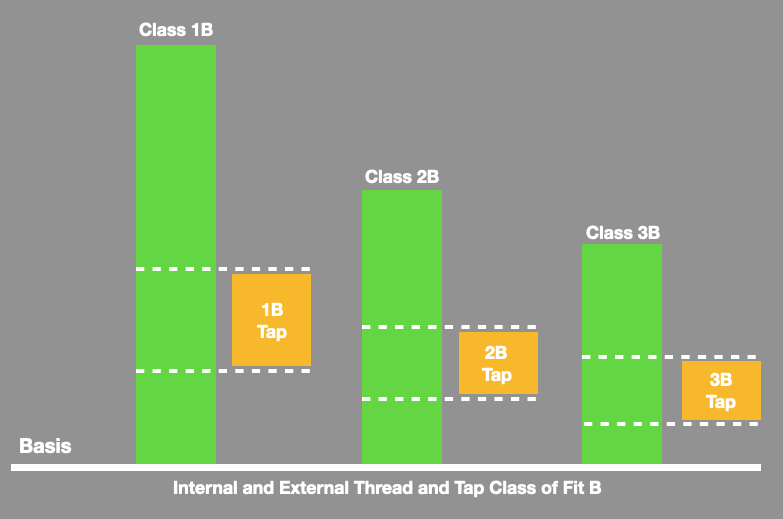
H limits are used to properly size a tap for the threaded hole to be produced. They are selected based upon the tolerance required for the part. These tolerances are defined by the symbols class 1B, 2B, or 3B.
The sizes of a 2B and a 3B tap are different. The 2B tap is smaller in size. It has an outside diameter of 0860 inches. The 3B tap is larger by .0130 inches, making its outside diameter .0990 inches. As the sizes progress up the tap scale, it increases in size by .0130 inches in outside diameter. Other types of taps, such as hand or fractional taps, increase in increments of 1/4 of an inch and referenced not as a number, but the size in inches
Selecting a H Limit on a tap
Once the class of thread and part tolerance has been defined, an H limit is selected to produce a thread that is within the minimum and maximum limits for that class if fit. These limits are the same as the Go and Not Go thread plug gage dimensions.
The goal is to select a tap with an H-limit that is near the middle of the part tolerance. For instance, if the total tolerance was .005", the tap should be approximately .0025" larger than the minimum limit of the part and .0025" smaller than the maximum. In order to handle the widest variety of tapping conditions, the "40% rule" is commonly applied. Using this rule, the tap is selected at 40% of the part tolerance. For instance, if the part tolerance is .005", multiplying .005" by 0.40 equals .002". Thus, the tap would be .002" larger than the minimum limit of the part or Go thread gage. With the position of the tap in relationship to the part tolerance established, the selection of an H limit number, such as H3, H4, H5, etc. is possible. H limits are a sequence of size "steps" in .0005" increments beginning at the minimum size limit of the part, starting with H1. In other words, an H1 limit is one .0005" increment larger than the minimum limit or Go gage, an H2 is two .0005" increments (or .001) larger than the minimum limit, an H3 is three .0005" increments (or .0015") and so on. In the example above, a tap that is .002" larger than minimum limit, is four .0005" increments larger, or an H4. This would be the tap H limit recommendation for this tolerance.
Taps are general marked with the appropriate tolerance class for their intended use. The U.S. GH thread class numbers are not marked on the tap.
Tolerances for the various GH numbers are shown in the chart below Classification for the tolerance 1B can be provided upon request. Taps for cast iron and titanium tapping are designed one GH class higher to provide better tool life. 
|
Technical Support BlogAt Next Generation Tool we often run into many of the same technical questions from different customers. This section should answer many of your most common questions.
We set up this special blog for the most commonly asked questions and machinist data tables for your easy reference. If you've got a question that's not answered here, then just send us a quick note via email or reach one of us on our CONTACTS page here on the website. AuthorshipOur technical section is written by several different people. Sometimes, it's from our team here at Next Generation Tooling & at other times it's by one of the innovative manufacturer's we represent in California and Nevada. Archives
July 2024
Categories
All
|
||||||||||||||||||||||||||||||||||||||||||||||||||||||||||||||||||||||||||||||||||||||||||||||||||||||||||||||||||||||||||||||||||||||||||||||||||||||||||||||||||||||||
 RSS Feed

About
|
© 2024 Next Generation Tooling, LLC.
All Rights Reserved Created by Rapid Production Marketing
|
