|
by Frank Twomey | OSG USA By switching to the AE-TL-N, Ross Industries has reduced about 75 percent of cycle time on the upper chambers and is now on average achieving a 150 percent cycle time reduction on other aluminum parts. 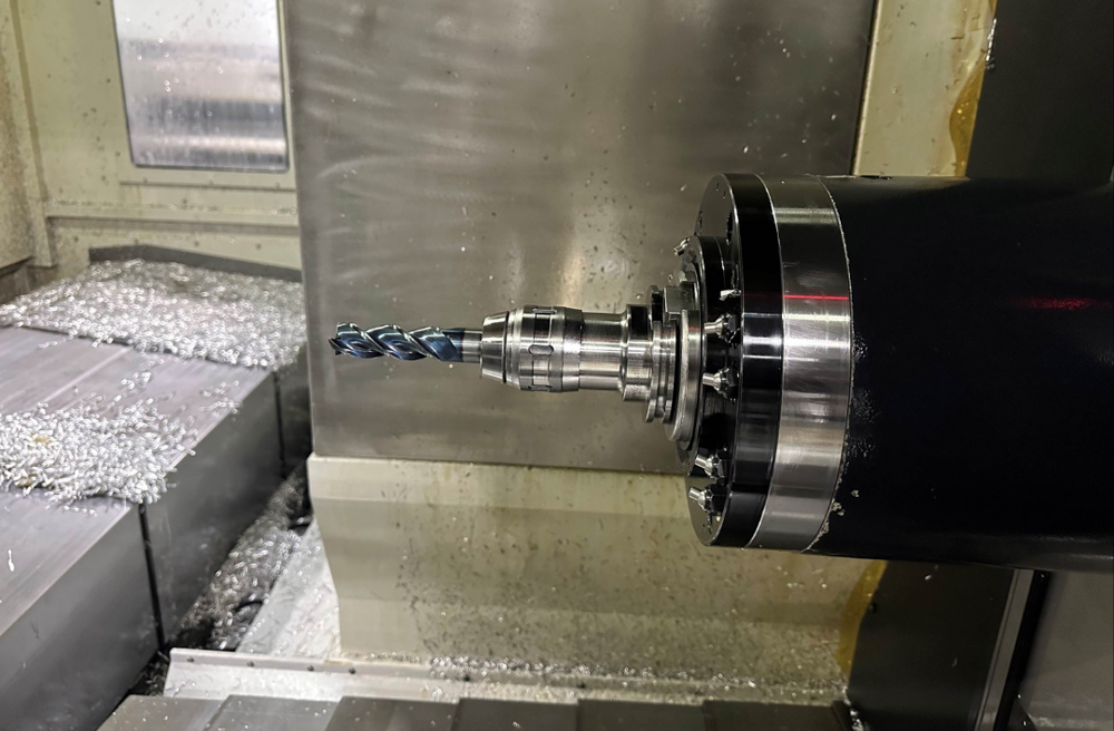 AE-TL-N DLC Coated Carbide End Mill Drives Greater Efficiency in Aluminum Part Processing Founded in 1968, Ross Industries, Inc. is a specialist in food processing and packaging solutions. Some of its key products include meat tenderizers, antimicrobial intervention systems, chilling and freezing equipment, formers and presses, slicers, macerators, tray sealing equipment, and more. All Ross systems are designed to help processors streamline food manufacturing and packaging functions to improve quality, productivity, and food safety while minimizing waste. With more than 50 years of industry expertise, Ross Industries has built an international reputation as one of the world’s finest food processing and packaging system providers. Employing approximately 100 staff, Ross Industries’ manufacturing plant is located in the city of Midland, Virginia, USA, with an estimate production area of 80,000-square-feet.  Founded in 1968, Ross Industries, Inc. is a specialist in food processing and packaging solutions. Employing approximately 100 staff, Ross Industries’ manufacturing plant is located in the city of Midland, Virginia, USA, with an estimate production area of 80,000-square-feet. Recently, Ross Industries was tasked with reducing cycle times on all of its aluminum parts. OSG Territory Sales Manager Frank Twomey has been in touch with Ross Industries through a distributor for about two years ago. In need to optimize productivity, OSG was given with an opportunity to test cut the upper chamber 6061 aluminum alloy part used in Ross Industries’ tray sealers for food packaging. 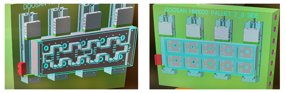 A CAD model of the front & back of the upper chamber, a part used in Ross Industries' tray sealers for food packaging Ross Industries has been producing these aluminum upper chambers for more than 25 years. Approximately 80 chambers are made annually along with thousands of other aluminum parts. The upper chambers are machined using a Doosan HM 1000 horizontal machining center with CAT-50 spindle taper. 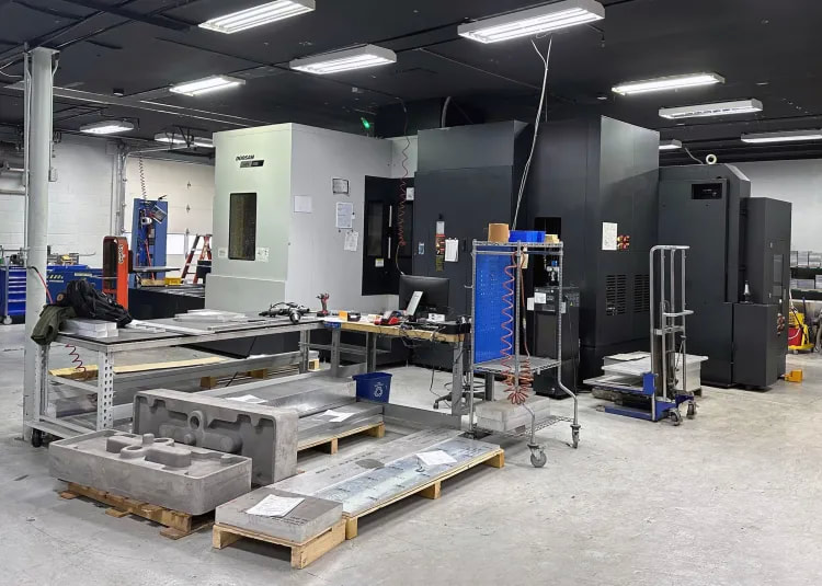 The upper chambers are machined using a Doosan HM 1000 horizontal machining center with CAT-50 spindle taper Ross Industries was originally using a competitor 1.5-inch diameter indexable shoulder cutter for the application. The competitor tool was used at a speed of 6,000 rpm (2,358 sfm, 717.8 m/min), a feed rate of 120 ipm (3,048 mm/min), 0.005 ipt (0.127 mm/t), 0.3-inch (7.62 mm) radial depth of cut, 0.375-inch (9.525 mm) axial depth of cut, and at a metal removal rate of 13.5 inch3/min (221.2 cm3/min). 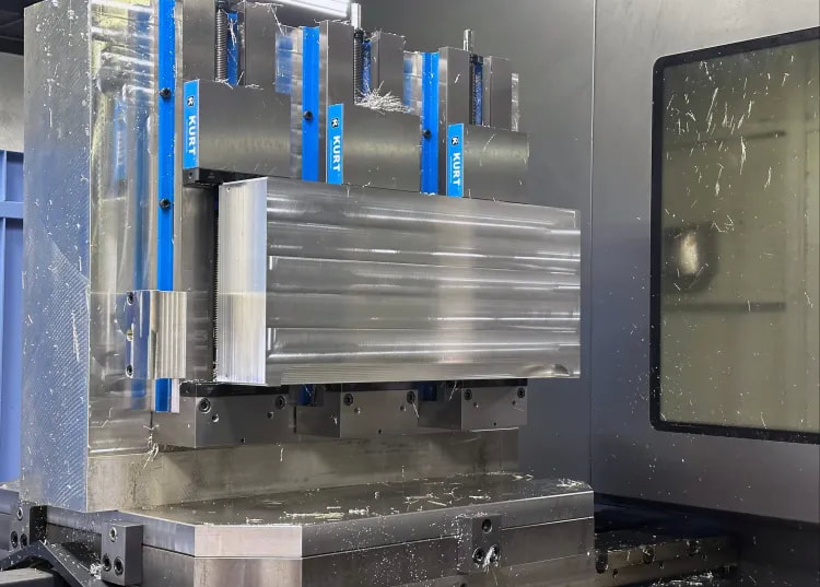 The upper chambers are made of 6061 aluminum alloy Upon a detail evaluation of the application, Twomey recommended OSG’s 3-flute 1-inch diameter AE-TL-N DLC coated square end mill (EDP# 86301809). The AE-TL-N DLC coated carbide end mill is extremely effective for non-ferrous materials such as aluminum alloys that require welding resistance and lubricity. With excellent cutting sharpness, it is able to suppress burrs to achieve superb surface finish. The AE-TL-N features a unique flute form to enable trouble-free chip evacuation and a large core design for high rigidity to prevent chattering. Its center cutting edge configuration enables the tool to be used for plunging. Furthermore, with the addition of OSG’s DLC-SUPER HARD coating, long tool life can be achieved. This end mill series is available in square, sharp corner edge and radius types to accommodate a wide range of applications.  The AE-TL-N DLC coated carbide end mill was tested at a speed of 5,125 rpm (1,343 sfm, 408.7 m/min), a feed rate of 231 ipm (5,867 mm/min), 0.015 ipt (0.382 mm/t), 0.14-inch (3.556 mm) radial depth of cut, 1.62-inch (41.148 mm) axial depth of cut, and at a metal removal rate of 52.39 inch3/min (858.5 cm3/min). Cycle time on the upper chambers went from 34.5 hours to nine hours. By switching to the AE-TL-N, Ross Industries has reduced about 75 percent of cycle time on the upper chambers and is now on average achieving a 150 percent cycle time reduction on other aluminum parts. 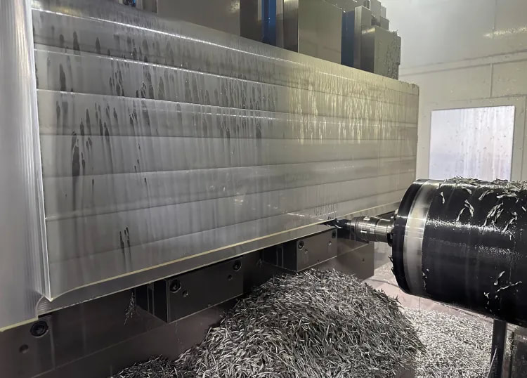 Switching to the AE-TL-N DLC coated carbide end mill, cycle time on the upper chambers went from 34.5 hours to nine hours. “This end mill creates chips so fast that our machines chip conveyors couldn’t keep up,” said Ross Industries Machine Shop Manager Greg Williams. “We had to speed up the conveyors.” Taken in consideration of factors such as tool change time, machine cost, labor, etc., it is estimated that an annual cost savings of $183,000 can be gained. In addition to the upper chamber part, Ross Industries has also converted all of its aluminum end mills to OSG’s AE-TL-N series in various sizes. 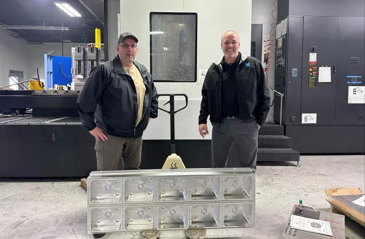 From left, Ross Industries Machine Shop Manager Greg Williams and OSG USA Territory Sales Manager Frank Twomey pose for a photograph with a completed upper chamber. “With the performance and consistent tool life of the AE-TL-N we are able to run these tools lights out,” said Williams. “In some cases, it is able to achieve as much as four times the metal removal rate versus the competitor tool.”
For more information on OSG’s AE-TL-N DLC coated end mill for non-ferrous materials and Ross Industries
0 Comments
by Peter Jacobs, via OSG USA blog There are almost as many distinct variations of CNC tools as there are finished products that could be milled. If you are familiar with the functions these tools perform, it will be much more straightforward for you to select the ones appropriate for the project you are working on. When it comes to the amount of time it takes and the quality of the work to be produced, choosing the appropriate cutting tool for your CNC milling machine, the material, and the type of milling can have a significant impact. So here is a list of prominent milling tools utilized for CNC cutting. 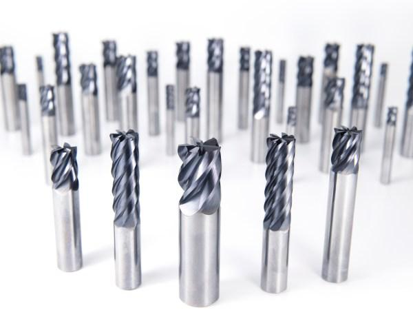 OSG HY-PRO® CARB VGM Series Different types of CNC milling tools make it feasible to achieve the highest level of product customization. While cutting into and shaping different types of materials, several tools are employed. The tool that should be utilized to cut also gets decided by the finalized design of the cut. Aside from these factors, specialists choose their tools based on how well they match the required speed with the desired finish. Depending on the ultimate purpose of the completed product, one of these two considerations might take precedence over the other. The top 7 milling tools for CNC cutting are: 1. End MillsThere are numerous kinds of end mills, each of which is designed for a particular kind of cutting. All end mills cut at an angle of ninety degrees. A center-cutting end mill is what's required to make a vertical cut. These mills can cut both the center and the margins of the workpiece. Non-center cutting end mills feature a hole in the middle of the tool and only contain cutting edges mostly along the ends of the mill. Since roughing end mills have fewer flutes than standard end mills, they are the tools of choice for making the initial cuts in a workpiece. You will need finishing end mills with additional flutes to obtain a design similar to the part you want to produce. It will enable you to deliver a component that is cut with immense precision. The tool employed on a project will vary depending on several factors, the most important of which is the number of flutes and the material of its composition. The production of end mills typically involves the use of cobalt, high-speed steel, and carbide as raw materials. More details about the different types of mills (as per their material) are given below.
End mills may perform a wide variety of cuts, the type of tool used depends on the type of cut being made:
2. Face MillsThis tool is primarily used to create a level surface on a solid portion of the material. As the first step in milling, this is often performed on the top of the stock to smooth it out. The cutter inserts in a face mill's sole body can be changed for specialized cutting tasks. You would require more cutters to remove metal at a faster rate. 3. Twist DrillsDrill bits resemble end mills in that they have a conical cutting tip on the end of a shaft with one or even more flutes. Twist drills are often made from solid carbide or High-Speed Steel (HSS). The drill's hardness, wear resistance, and lifespan can be improved by applying a gold-colored coating, such as TiN. 4. Fly CuttersFly cutters are considered the best to create a fantastic surface finish. The clockwise motion of these cutting tools produces a mirror-like finish on the material. 5. Center Spotting DrillsThese stocky tools first construct a precise conical hole to avoid the drill bit from drifting during a cutting operation and end up drilling the hole at an incorrect site. Screw clearance holes and counterbores can be drilled with the same tool thanks to multi-function drills that spot and countersink. 6. ReamersReamers are mainly utilized to enlarge the existing holes in compliance with the tolerance while providing a superior surface finish. They help you ensure the accuracy of the roundness and diameter of a drilled hole. For reamers to work, a pilot hole of roughly the same diameter as the final product must first be bored. 7. Taps and Thread MillsTaps are tools used to cut threads into the interior of a material. Yet not every thread is produced by a cutting procedure. By applying pressure, Roll Form taps get inserted into holes, and the surrounding material is shaped to fit them. Thread mills are similar but can be employed to cut internal or external threads. Concluding RemarksThe key to successfully machining products and components is selecting the appropriate CNC tool. Learn how each one functions, and keep in mind the use of the most beneficial ones in your manufacturing facility. About the AuthorPeter Jacobs is the Senior Director of Marketing at CNC Masters. He is actively involved in manufacturing processes and regularly contributes his insights for various blogs in CNC machining, 3D printing, rapid tooling, injection molding, metal casting, and manufacturing in general.
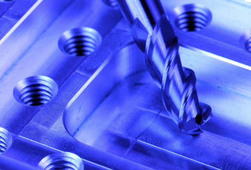
Small Diameter Coolant-Through Carbide Drills 2D · 5D · 12D · 20D · 30D OSG Corporation has announced the release of the ADO-MICRO small diameter coolant-through carbide drill series for stable and high efficiency drilling in small diameter deep-hole applications. 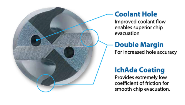 The ADO-MICRO features a unique double margin geometry with an extended flute and shortened end margin to enhance chip evacuation capability Poor chip evacuation is a common complication in small diameter deep-hole drilling. Micro sludges can be easily accumulated around the outer periphery of the cutting tool, which is a key cause of abrupt tool breakage. The ADO-MICRO features a unique double margin geometry with an extended flute and shortened end margin to enhance chip evacuation capability. In addition to the outstanding chip ejection performance, the double margin configuration supports the straightness stability of the tool and reduces rifle marks on the inner surface of holes. Furthermore, the ADO-MICRO features a pair of large oil holes and employs a hollow shank design to allow large coolant flow volume for trouble-free chip evacuation. The ADO-MICRO is coated with OSG’s original IchAda coating that provides excellent surface smoothness in conjunction with high abrasion resistance and heat resistance to enable small diameter tools to achieve long tool life. With the ADO-MICRO’s unique tool geometry and IchAda coating, non-step drilling is made possible even for deep-hole applications, enabling high processing efficiency. 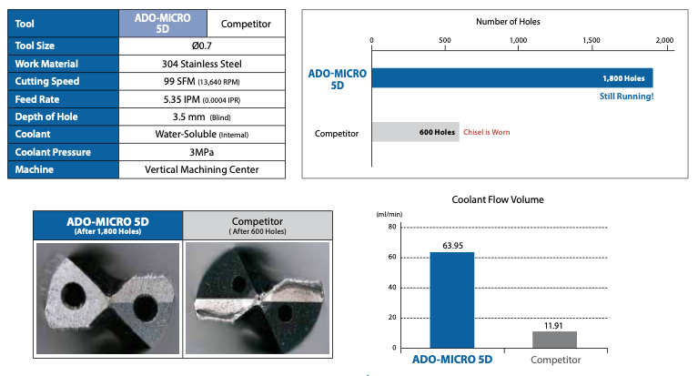 The ADO-MICRO’s large coolant holes increase the coolant flow volume resulting in stable drilling The ADO-MICRO is suitable for carbon steel, alloy steel, stainless steel, cast iron, ductile cast iron, aluminum alloy, titanium alloy and heat resistant alloy. The ADO-MICRO is available from diameter 0.7 mm up to 2 mm for drill lengths 2xD and 5xD, and diameter 1 mm to 2 mm for drill lengths 12xD, 20xD and 30xD. Got an application you want to try this on? Give us a call! We've assembled a few tips on drilling that you may want to pass along to your team. Drilling Tip 1 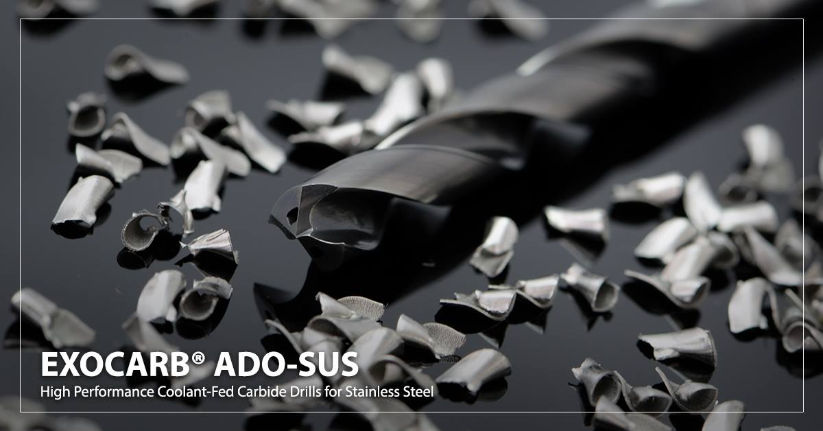 During drilling operations, chip formation is very important to keep an eye on. If you are getting long unbroken chip with jagged edges, your feed rate is too high. If you are getting tight spirals but the chips are not breaking apart, your feed rate is too low. The Ideal chip shape is small tight curls, Like little "6's and 9's". When you are getting these shapes of chips then you will get best tools life and finish on your part. Drilling Tip 2  If your drill is getting chipped only on one edge or if your drill has more wear on one cutting edge than the other, the cause could be bad run out of the drill or bad alignment of the machine. This means one side of the drill is experiencing more axial forces than the other. If you correct the run out of the drill and alignment of machine spindle, the problem will be solved. Drilling Tip 3  If your drill has too much run out, you will have issues such as hole expansion, bad hole perpendicularity, and poor surface finish. Drill run out should be less than 0.0008"(0.02mm) when setting up. The run out increases with the speed, thus, when drilling a deep hole. OSG recommends making the pilot hole 0~0.003"(0.08mm) oversize and inserting a long drill at 0~500rpm so that the drill is fitting properly in the pilot hole . Drilling Tip 4 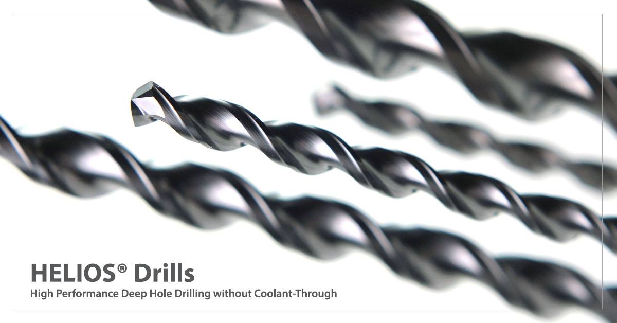 The V-Series HELIOS® drill is the 1st drill to process deep holes 10X-20X diameter, without pecking and without the use of internal coolant supply. Flute form, point thinning and compound lead construction are all patented technologies developed by OSG to make this drill do what no other parabolic HSS-Co drill can. The addition of our exclusive WXL coating technology makes non-peck drilling repeatable, even in the longest of production runs. Drilling Tip 5 Last but not least, don't forget that now through August 31st, save 12% on select A-Drills!l 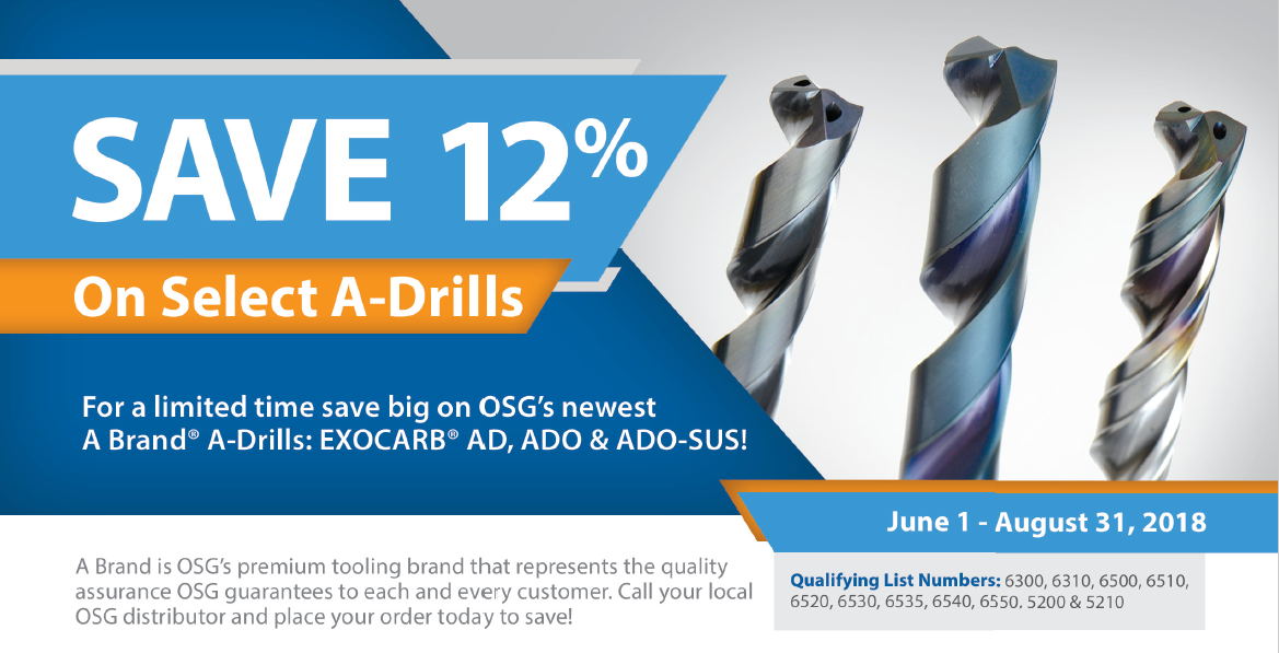 An end mill is a type of milling cutter. It is distinguished from the drill in its application, geometry, and manufacture.
End mills are used in milling applications such as profile milling, tracer milling, face milling, and plunging. Below is a great video of how OSG makes end mills. It takes you through the process from design to the grinding operations and through inspection. Check it out! ...and below is the segment from "How It's Made" that covers the more general principles of making a HSS end mill. You can see that OSG has a very advanced process for making their carbide end mills.  Mark Your calendar: May 10, 2016 and join us in Los Angeles for Aerospace Composites & High Temperature Alloys Training OSG's Aerospace training for composites & high temp alloys covers: Difficulties when machining, troubleshooting, the best tools for aerospace machining and more! What You’ll Learn
Who Should Attend: This seminar will benefit anyone curently machining or interested in learning more about machining composites and high temp alloy materials. Machinists, operators, manufacturing engineers, programmers, etc. Seminar Agenda
9:00 - 12:00 - Composites
1:00 - 4:00 - High Temp Alloys
by David Aly, Aerospace Specialist, OSG Tap & Die Just because you’ve tried one forming tap, doesn’t mean you’ve tried them all. We had the recent opportunity to prove that OSG forming taps are better than the rest. As a supplier of custom fabricated metal products and machinery, one of our customers approached us wanting to get better chip control during their tapping operation. Located in Winona, Mississippi, they have a 92,500 square foot manufacturing facility for producing fuel tanks, hydraulic tanks and custom designed machining fixtures. 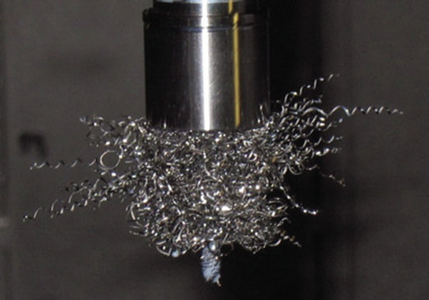 A common problem with cut taps is the rats nest that is created when cutting more ductile materials. A Roll Form tap doesn't create chips, so the problem is eliminated After discussing the customer’s chip control needs, I recommended OSG’s EXOTAP® NRT® Forming Tap, a more stable, thread rolling tap that makes threads by compressing the work material without creating chips. Because no chip is produced, breakage due to chip packing and bird nesting is eliminated. The EXOTAP® NRT® also has significantly reduced friction resistance because of its special threading design and surface treatment. Made from VC-10 Powdered Metal High Speed Steel, this forming tap has a longer tool life when tapping difficult to machine materials like carbon steels, alloy steels, stainless steels and aluminum alloy. 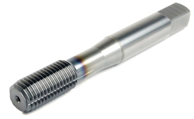 OSG’s EXOTAP® NRT® Forming Tap is a Roll Form Tap extrudes the thread form by displacing material. The Groove serves two function: Permitting lubricant to reach the lobes of the tap while forming and to permit air to escape from the bottom of a blind hole during the tapping process. Initially, the shop foreman, Mr. William Smith, was hesitant about using a forming tap due to a bad experience with a competitor’s brand. After I showed William a presentation and a chip flow demonstration video, he was willing to give our forming tap a chance. We approached his staff with OSG’s EXOTAP® NRT® Forming Tap in hand. After explaining the test with the operator and reiterating that there will be no chips, we began the trial. A few days later, I called to check in on their progress. William enthusiastically explained that he was still running the same tap. He had lost count of the number of holes produced but assured me that it was well over 1,000 holes! After such a successful run with the first test tap, he purchased more of the test size, now truly convinced that all forming taps are not created equal.
Next Generation Tooling is excited to offer some new services coming in 2015! Below is a very fast video of our new training series on Tapping which we can present to your manufacturing team at your site. It's a comprehensive overview of screw thread terminology, thread forms, fundamentals of threads, classes of fit, Tap basics, types of chamfers, the tapping process,tap types, screw thread inserts, helix angles, core diameters, re an hook angles, thread reliefs, pitch tolerances, H limits, Tap substrates, Surface treatment and coatings, tapping speeds, tap drill sizes.
|
Technical Support BlogAt Next Generation Tool we often run into many of the same technical questions from different customers. This section should answer many of your most common questions.
We set up this special blog for the most commonly asked questions and machinist data tables for your easy reference. If you've got a question that's not answered here, then just send us a quick note via email or reach one of us on our CONTACTS page here on the website. AuthorshipOur technical section is written by several different people. Sometimes, it's from our team here at Next Generation Tooling & at other times it's by one of the innovative manufacturer's we represent in California and Nevada. Archives
July 2024
Categories
All
|
||||
 RSS Feed

About
|
© 2024 Next Generation Tooling, LLC.
All Rights Reserved Created by Rapid Production Marketing
|
