 The number of flutes on a carbide end mill significantly influences its performance across various machining applications. How many flutes do you need? The simple answer: It depends. Obviously there are a quite a number of other factors that impact an end mills performance such as helix angel, edge prep, gullet depth and radius. We can't tackle everything in this article, but hopefully this helps you get a better understanding of why there are different numbers of flutes on end mills. Below is an overview of the advantages and disadvantages associated with end mills featuring different flute counts, along with recommendations for materials based on ISO 513 categories (P, M, K, N, S, H) Single Flute End Mills
2-Flute End Mills
3-Flute End Mills
4-Flute End Mills
5-Flute End Mills
6-Flute End Mills
7-Flute End Mills
8-Flute End Mills
0-Flute End Mills
Advantages of Higher Flute Counts in |
| Much of this burden falls on the holder. Balance doesn’t change as spindle speed increases, however the forces it creates increase exponentially alongside speed. The impacting results appear quickly in micromachining. When runout occurs, the edge most affected takes over the bulk of the cutting. Uneven wear causes the tool to fail more quickly than if the tool rotates about the centerline as intended. In one customer application, we found that drilling into a steel workpiece 0.590" deep with a 0.118" diameter carbide drill in a holder with 0.00008" runout accuracy produced 2,300 holes. | 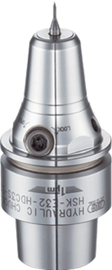 Micro milling machines, ideally suited for small tools and small workpieces, are characterized by spindle speeds of more than 50,000rpm using small HSK tool holders such as HSK-E32, E25, or E20. |
Holder attributes that can boost production include symmetrical design, a perfectly concentric collapse of the collet around the cutter, and a ball-bearing raceway nut with precision-ground threads.
While these characteristics are good rules of thumb, things change fast in this field and, like our customers, we must adapt as trends emerge.
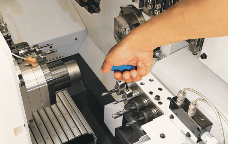
Batch sizes are getting smaller. Bone screws, for example, were typically run on multi-axis, Swiss-type lathes where the same tools and programs ran for days at a time. Traditionally, prototyping in this arrangement was not an option because of the complexity and time involved in programming and setup. Today’s need for customized sizes demands flexibility and quick changeover to remain productive.
We are investing a large portion of our research and development (R&D) in tackling this challenge. We are working on hydro-clamping tool holder systems that could make the decades-long approach of using ER collets obsolete. It would make it possible, for example, to perform a simple drill change on a gang slide in seconds.
Another trend in medical manufacturing being driven by the U.S. Food and Drug Administration (FDA) is clean machining without the use of water-soluble coolants.
| Super-chilled CO2 or cryogenic machining with liquid nitrogen are considered possible replacements. Protecting small holder parts at the nose from coolant has always been a concern, but using gas requires more attention for holders to be effective. | 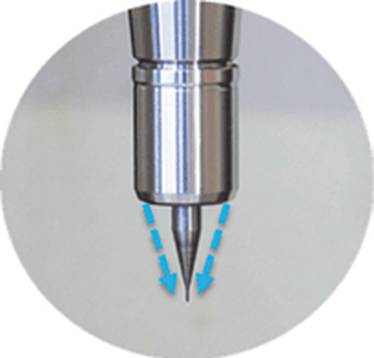 The Mega Micro Coolant Nut for Mega Micro Chuck 6S provides a more efficient coolant supply for micro cutting tools and is designed for high-speed micro machining up to 6mm. |
- Holders that remain completely sealed to outside atmosphere
- Very small delivery holes in collet faces or clamping nuts that properly restrict gas flow
Tool considerations also must be taken into account to keep up with the demanding medical field. Better results often cannot be achieved by simply increasing spindle speeds or using smaller tools; a deeper understanding of cutters is necessary.
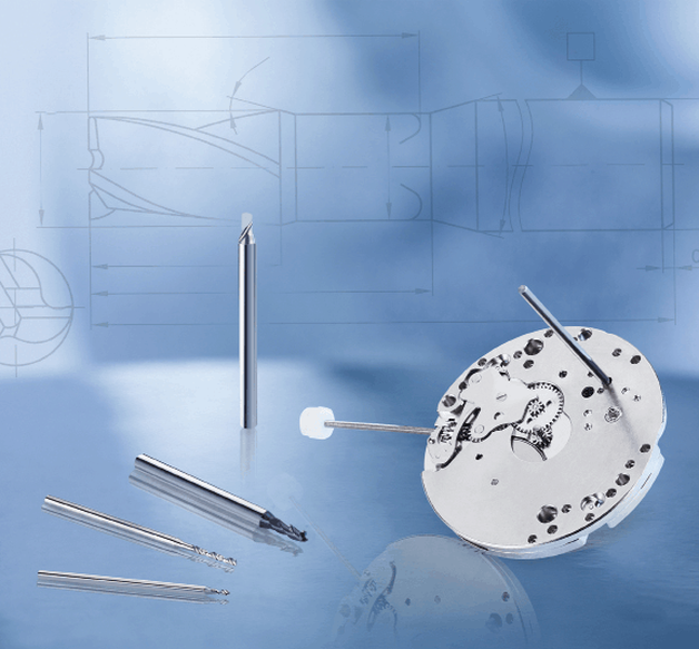
We consider tools with diameters <3mm to be micro tools. These aren’t simply smaller versions of their macro counterparts. They have geometric considerations all their own. For example, the 1mm Sphinx drill can run at 80xD. But this is only possible because the cylindrical shaping extends further down the tool, closer to the tip, to facilitate pecking and maintain strength.
Tool carbide should be ultra-fine grain (nano or submicron grain size) to ensure high abrasion resistance and good toughness. Coatings are valuable too, but it’s important to understand how coatings can negatively impact micro tool performance. Micro tools have extremely fine surface finishes and sharp cutting edges. Coatings can fill in valuable space – a flute on a drill, for example – needed for proper chip evacuation, which is critical in these applications.
Coatings must be ultra-thin (<1µm) and smooth; our experience shows that misapplied coatings result in poor tool life due to breakage; the coating reduces cutting edge sharpness, increasing torque force on the drill. When coating is necessary, consult with the cutting tool manufacturer to provide this directly.
Chips and small tooling naturally do not get along well. Compensating for low spindle speeds with tools that have more flutes support an ideal feed rate, but chip evacuation may suffer. Determining the appropriate chip load – as close to the cutting edge as possible – allows operations at the highest possible spindle speed, accelerating the cycle and improving surface finish.
Optimal conditions exist when the chip load is relatively equal to the cutting edge radius.
Many micro end mills are designed so the cutting edge radius has a positive rake angle to create a shearing action. A chip load less than the cutting edge radius often results in a negative rake angle where the tool rubs rather than cuts. This increases the force required and generates more heat which can result in built-up edges and poor tool life. A chip load significantly bigger than the cutting edge radius often leads to premature failure because the tool is not robust enough to withstand such forces.
Micromachining requires machine tools with very high sensitivity, fine resolution in the feed axis, and very precise spindles capable of high speed with low dynamic runout. For micro-drilling operations, specialized micro machines are best.
Micro milling machines are suited for small tools and small workpieces. They are characterized by spindle speeds faster than 50,000rpm using small HSK tool holders such as HSK-E32, E25, or E20. With the right holder, tool runout can be controlled to less than 1µm (0.000040") at the cutting edge, ensuring sub-micron accuracy.
In medical micromachining, understanding each piece of the equipment puzzle is critical. It’s also important not to make assumptions based on other tools or parts you may have worked with, especially in more standard sizes. Invest the right time and energy in gearing up for the next medical job and you’ll get more parts done right faster.
| An argument can be made for balancing almost every tool put in a machine. In the world of rotating tools, small changes to an assembly, like a new cutting tool, collet, nut or retention knob, can put an assembly out of tolerance. Therefore, it stands to reason that any unbalance could translate to the part, tooling and/or machine spindle in harmful ways. You’ll hear the case for balancing every single tool based on the long-standing ISO 1940-1 standard. | 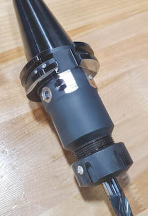 Balancing a toolholder several times causes the toolholder to become excessively modified. It's OVERBALANCED |
However, machines were much slower 80 years ago. Back then, the most advanced machines would have spun larger, heavier tools at a maximum speed of about 4,000 RPM. If you applied the math from those days to today, you’d get unachievable values.
For example, the tolerances defined by G2.5 for tools with a mass of less than 1 pound rated for 40,000 RPM calculates to 0.2 gram millimeters (gm.mm.) of permissible unbalance and eccentricity of 0.6 micron. This isn’t within the repeatable range for any balance machine on the market.
Similarly, application-specific assemblies, for operations like back boring and small, lightweight, high-speed toolholders, can’t be accurately balanced for G2.5.
Machine tool builders rely on an outdated number, too, often basing spindle warranty coverage on using balanced tools at very specific close tolerances. While it’s true that poorly balanced tools run at high speeds wear a spindle faster, decently balanced tools performing common operations won’t wear spindles or tools drastically and deliver the results you’re looking for.
A Little Lesson About Forces
| In other words, if you’re rough milling with a heavy radial cut, the different forces will start bending the tool. When that happens, the cutting forces and all the feed forces will be substantially higher than whatever the unbalance forces might be. If that’s the case, it’s not that you take the unbalance force and add it to the cutting force and find your adjustment. | 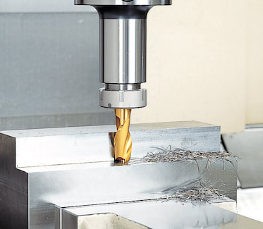 Big Kiaser New Baby Chuck and Mega New Baby Chuck are balanced for High speed machining. The Precision collet is guaranteed to produce a maximum runout of only 1 micron at the collet nose. |
Unbalanced tools are also blamed for issues that turn out to be misunderstandings about a machine’s spindle. I’ve visited shops with new high-speed spindles that had trouble running micro tools over 15,000 RPM. They rebalanced all the tools on the advice of their machine tool supplier, but to no avail. It turned out the machine was tuned for higher torque and higher cutting forces. Before going to the effort of balancing toolholders, work with your machine builder to understand where a spindle is tuned.
Not only is balancing tools rarely necessary, it can also be risky. Our inherently asymmetrical fine-boring heads are a good example. Because we balance them at the center, a neutral position of the work range, you lose that balance if you adjust out or in.
To adjust, you’d typically add weight to the light side, which can be a problem for chip evacuation and an obstructor. Or you can remove weight from the heavy side, but that means you have to put some big cuts on the same axis of the insert and insert holder, ultimately weakening the tool.
In longer tool assemblies, common corrections made for static unbalance can also cause issues. It happens when a toolholder is corrected for static unbalance in the wrong plane; i.e., adding or removing weight somewhere on the assembly that’s not 180 degrees across from the area where there’s a surplus or deficit.
Once the tool is spun at full speed, those weights pull in opposite directions and create a couple unbalance that often worsens the situation.
A Cautionary Tale
As a cautionary tale, consider a customer who was attempting to balance a batch of our coolant-fed holders. Based on the balancing machine, the operator drilled ¼-inch holes at the prescribed angle into the body of the holders. Not realizing what was inside, he drilled into cross holes connecting coolant flow and ruined several holders.
Tooling manufacturers are doing their part to avert disasters like this. For most, simple tools like collet chucks or hydraulic chucks are fairly easy to balance during manufacturing. We account for any asymmetrical features while machining and grinding holders and pilot each moving part, ensuring they’ll locate concentrically during assembly. These measures ensure the residual unbalance of the assemblies is very, very low and eliminate the need for balancing.
| Auto-balancing boring heads are designed specifically for the high-speed finishing I mentioned earlier, where unbalance force can be greater than cutting force. Our EWB boring heads, for instance, have a small internal counterweight that moves in direct proportion with each adjustment. Because the weight is carbide, it’s three times more dense than the steel in the tool carrier and is maintained inside the head’s symmetrical body. | 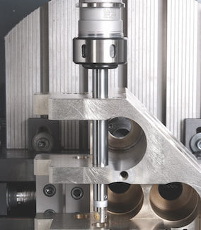 Autobalance boring heads, Series 310 EWB, maintain perfect balance throughout the work range due to the integrated counter-balance mechanism. Even at maximum speeds, balanced tools guarantee vibration-free boring, resulting in increased productivity and high precision. |
Save your balancing time and resources for high-speed fine finishing. If you do have work where balance is crucial, consider how the tools you buy are balanced and piloted out of the box and/or consult your partners before making any modifications.
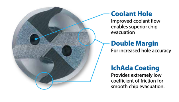
The ADO-MICRO features a unique double margin geometry with an extended flute and shortened end margin to enhance chip evacuation capability.
In addition to the outstanding chip ejection performance, the double margin configuration supports the straightness stability of the tool and reduces rifle marks on the inner surface of holes.
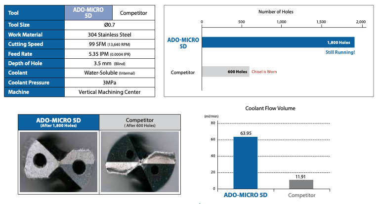
Furthermore, the ADO-MICRO features a pair of large oil holes and employs a hollow shank design to allow large coolant flow volume for trouble-free chip evacuation.
The ADO-MICRO is coated with OSG’s original IchAda coating that provides excellent surface smoothness in conjunction with high abrasion resistance and heat resistance to enable small diameter tools to achieve long tool life.
With the ADO-MICRO’s unique tool geometry and IchAda coating, non-step drilling is made possible even for deep-hole applications, enabling high processing efficiency.
Got an application you want to try this on? Give us a call!
Technical Support Blog
We set up this special blog for the most commonly asked questions and machinist data tables for your easy reference.
If you've got a question that's not answered here, then just send us a quick note via email or reach one of us on our CONTACTS page here on the website.
Authorship
Our technical section is written by several different people. Sometimes, it's from our team here at Next Generation Tooling & at other times it's by one of the innovative manufacturer's we represent in California and Nevada.
Archives
March 2024
February 2024
January 2024
December 2023
November 2023
October 2023
September 2023
August 2023
July 2023
June 2023
May 2023
April 2023
March 2023
February 2023
January 2023
December 2022
November 2022
October 2022
September 2022
August 2022
July 2022
June 2022
May 2022
April 2022
March 2022
February 2022
December 2021
November 2021
October 2021
September 2021
August 2021
July 2021
June 2021
May 2021
April 2021
March 2021
February 2021
January 2021
December 2020
November 2020
October 2020
September 2020
August 2020
July 2020
June 2020
May 2020
March 2020
February 2020
January 2020
September 2019
August 2019
July 2019
June 2019
May 2019
March 2019
January 2019
September 2018
June 2018
April 2018
February 2018
December 2017
November 2017
October 2017
August 2017
June 2017
April 2017
March 2017
February 2017
January 2017
December 2016
November 2016
October 2016
August 2016
March 2016
February 2016
January 2016
November 2015
August 2015
July 2015
May 2015
April 2015
March 2015
November 2014
August 2014
July 2014
December 2013
November 2013
September 2013
July 2013
March 2013
December 2012
March 2012
November 2011
May 2011
March 2011
January 2011
December 2010
November 2010
October 2010
Categories
All
5th Axis
Aerospace
Allied Machine
Aluminum Oxide
Angle Head
AT3
Balance
Bellmouthed Hole
Big Daishowa
Big EWA Automatic Boring
Big Kaiser
BIG Plus
Blue Photon
Bone Screws
Boring Tool
Carbide
Carmex Precision
CBN
Centerline Deviation
Ceramic Black
Ceramic End Mill
Ceramic Inserts
Ceramic Oxide
Ceramic Whiskered
Ceramic White
Chamfer
Champion Tool Storage
Chip Breaking
Circular Saw
Class Of Fit
CNC Lathe Tooling
Collet
Collet Chuck
Collet ER
Collet TG
Composites
Covid-19
Deep Hole Boring
Deep Hole Drilling
Drilling
Dual Contact
Dyna Contact Gage
Dyna Force Tool
Dyna Test Bar
EMO
End Mill
Exotap
Facemill
Fixturing
Fretting
Gaylee Saw
Hard Turning
Heimatec
Helical Interpolation
Hohl Shaft Kegel
How Its Made
HSK A
HSK-A
HSK E
HSK-E
HSK F
HSK-F
HXL Tap
Hy Pro Tap
Hy-Pro Tap
IMTS
Jergens
Kurt
Lang
Live Tooling
MA Ford
Maintenance Cart
Mapal
Martindale Saw
Material: Aluminum
Material: CFRP
Material: D2
Material: Hastelloy
Material: Inconel
Material: Peek
Material: Stone
Material Titanium
Material: VC 10
Material: VC-10
Metric Course Thread
Metric Fine Thread
Metric Thread Chart
Microconic
Micromachining
ModLoc
Modular
Mogul Bars
MPower
No Go Too Loose
NTK
NTK HX5
On Site Training
OptiMill-SPM
OSG Tap & Die
Oversized Thread
Parlec
PCD
PCT Firm Hold
Platinum Tooling
Projection Length
Pull Studs
Reamer
Retention Knob
Rotary Toolholders
Rotary Toolholders BT
Rotary Toolholders CAT
Rotary Toolholders HSK
Rotary Toolholders Hydraulic
Rotary Toolholders Shrink
Rough Thread
Runout
Runout Axial
Runout Radial
Safe-Flex
Saw Selection
Short Tap Life
Sialons
Silicon Nitride
Smart Damper
Speed Increaser
SpeedLoc
Speroni STP Essntia
Spindle Mouth Wear
Surface Roughness Ra
Surface Roughness RMS
Swiss
Swiss Machining
Taper Wear
Tapping Feed
Tapping; Form
Tapping IPM
Tapping: Roll
Tapping RPM
Tapping Speed
Tap Tolerance
Technical Training
Technicrafts
Techniks USA
Thread Milling
Thread Whirling
T.I.R.
Tolerance
Toolchanger Alignment
Toolholder Taper
Tool Presetter
Torn Thread
Troubleshooting
UNC Thread Size
Undersized Thread
UNF Thread Size
Unilock
Vises
Washdown Tool
Workholding
 RSS Feed

About
|
© 2024 Next Generation Tooling, LLC.
All Rights Reserved Created by Rapid Production Marketing
|
