NEXT GENERATION TOOLING
  • Home
    • Schedule
    • Training
  • About
    • History
    • Contact
  • Territories
    • NorCal & N-NV
    • SoCal & S-NV
    • Mountains
  • Principals
    • Tooling >
      • 2V Industries
      • BIG Daishowa
      • Champion Storage
      • Drill America
      • Jewell Group
      • Mapal
      • Martindale Gaylee
      • OSG Tool
      • Performance Micro Tool
      • Platinum Tooling
      • TechniksUSA
    • Workholding >
      • BIG Daishowa
      • Earth Chain
      • Jergens
      • mPower Workholding
  • Promotions
  • Events
  • News
  • Technical

Next Generation Tooling Now Offers Technical Training!

6/14/2017

3 Comments

 
We are very excited to announce that we are now able to offer on-site technical training to YOUR machinists at YOUR location!  This is offered at no charge  to customers who use any of the manufacturer's whom we represent in California and Nevada.  

However, just because you don't purchase things from us, don't feel left out! We also offer on-site topic specter training on any of the following topics for $150/hour.  

Each presentation lasts about 2 hours.  The presentations last approximately 45-60 minutes with the remaining time for Q&A and discussion about unique applications in your facility.
Picture
Training Classes Available:
Machining 101
  • Basic Boring
  • Basic Chamfering
  • Basic Drill Training
  • Basic End Mill
  • Basic Indexable
  • Basic Tap Training
  • Basic Tool Holders
  • Basic Work Holding / Fixturing​

Advanced Part Manufacturing:
  • Programming Tool Path – Climb versus Conventional
  • Material Machinability – Cubic Inches of Stock Removal
  • Part Set Up / Work Holding / Fixture 
  • Tool Holder Selection, Collet, Solid, Hydraulic, Shrink Fit
  • Cutting Tool Selection – Substrate, Geometry, Coating, Speed and Feeds 
  • Estimating Part Cycle Time
3 Comments

Real Thread Whirling in Bone Screws

7/16/2014

1 Comment

 
 This article originally appeared in decomagazine March 2013 entitled "Real Thread Whirling"  Edited  September 30, 2020 by Bernard Martin to add new video and additional content.
Picture
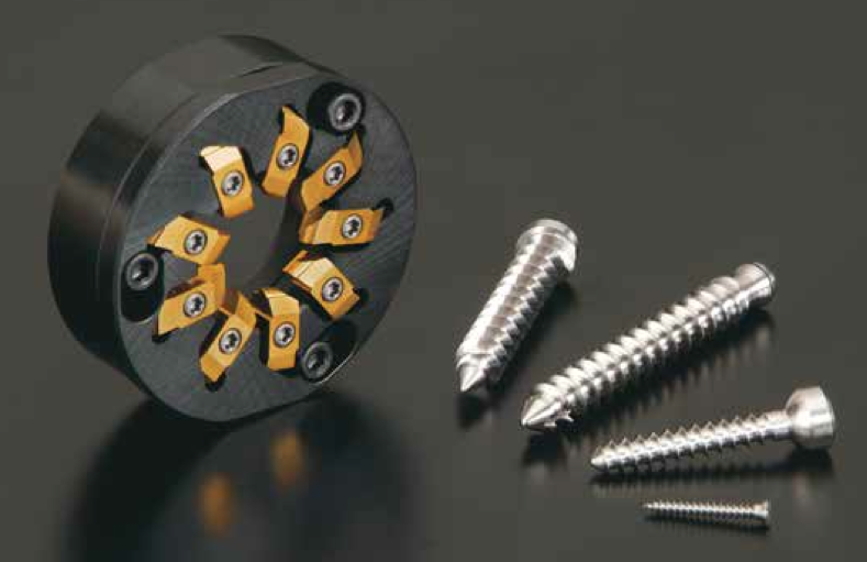
“Thread Whirling” has become a popular process for Swiss machines, especially among bone screw manufacturers. Although most Swiss machine engineers agree that thread whirling delivers outstanding productivity with the highest efficiency vs conventional single point threading, not all engineers know the “Real Thread Whirling” process. 
NTK first released thread whirling tools with (9) inserts back in 2008. NTK engineers never perceived thread whirling as a complicated process. 

The complication was not with regards to machining difficulty but in producing the perfect thread form described on the print itself.

The so called “Bone Screw” is a major part produced by the thread whirling process. It is quite unique, compared with the other industrial screws, since there are no female threads to mate.  
Bone screws are attached directly into human or animal bones for medical repair applications. The screw is not expected to be loosened at all once it is fixed in place. The characteristics of bone screws are: larger pitch size and larger screw depth and length as their key function is to be tightened into bones rigidly and as quick as possible.

As a result of this uniqueness, inspection of screw forms has become extremely difficult. Due to the larger helix angle to make a high pitch thread form, you cannot visually see the cross section at all with a common optical comparator. What you can check with an optical comparator is only the peripheral or bottom diameter of the thread.
Bone Screw Thread whirling Titanium 6al4V
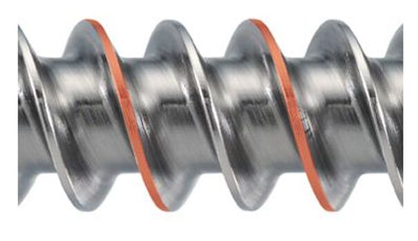
6AL-4V Titanium Bone Screw that has been created via Thread whirling
The only way to measure the real thread form of a bone screw is to inspect it with a (CMM) Coordinate Measuring Machine. However, there are not many manufactures which use CMM type of measurement  machine for the inspection after machining. Most of them focus on visual inspection of thread form and surface roughness and use an optical comparator for the final inspection.  

Another surprise for NTK engineers, is the fact that even in manufacturers that have the very latest machines, well experienced and highly educated staffs, the engineers make small adjustment on a helix angle or pitch size when they cannot get the ideal thread form.
Carbide Insert Bone Screw Thread whirling Titanium 6al4V
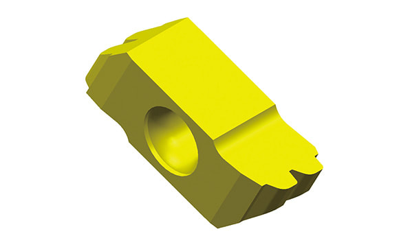
Thread whirling carbide Insert for the 6al4V Titanium Bone Screw pictured
As you may understand, if you change the helix angle or pitch size, thread form itself could be totally out of print specifications. 

Why does this happen? One factor comes from the uniqueness of bone screw: There is no female thread. That is, if the thread form is made close enough to the print, the screw can perform its function to be tightened rigidly to a bone since there is no mating surface (female thread). The other comes from difficulty in designing thread whirling inserts due to complexity of thread form itself.
Having a visual image of thread whirling process in your mind is extremely difficult. Thread whirling inserts are set on the round cutter body and the cut- ter is attached to the spindle which is tilted with a helix angle. The spindle revolves at a higher rotation (like 3000 rpm) while the bar stock revolves in the same direction but at a much slower rate like 10-30 rpm.

During this rotating process, each thread whirling insert machines the bar stock while they rotate much faster than the bar stock. The spindle and the inserts tilt to make thread form and the inserts shave or cut bar stock not only at the center of the bar stock but also the upper or the lower side of the bar stock.  
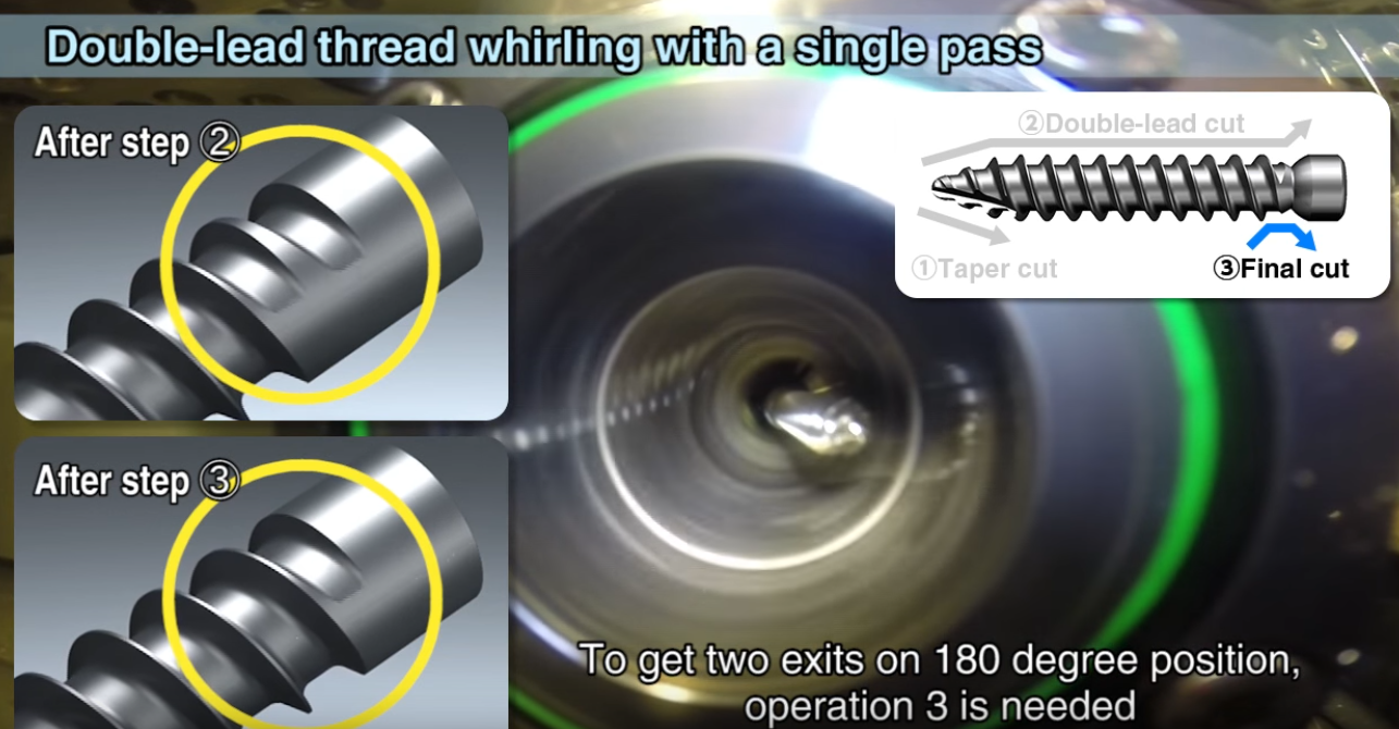
NTK Thread Whirling -Machine a double lead screw in a single pass
Conventional, single point threading inserts are designed with exactly the same thread form as the thread itself because it always machines with regards to the center of the bar stock.

On the other hand, thread whirling inserts cannot be designed with the same concept because the actual machining point always varies on the upper or lower side of the bar stock. However, there are some competitor’s thread whirling inserts designed with the identical methodology as single point threading.

With this incorrectly designed thread whirling inserts, bone screw manufactures are frequently required to re-make the inserts, in some cases, not one time but several times. Or, they are forced to make inappropriate manual adjustment on the helix angle or pitch size to obtain the thread form which looks closer to the prints specification. 

NTK thread whirling does not require such guesswork process manipulation. Thanks to the design capability of our inserts we can obtain perfect threads right from the start. This process designing technology is now patented. 
Recently, to reduce surgery hours, bone screws with double lead threads are becoming more popular. This industry trend is creating another challenge for most bone screw manufacturers. Producing double lead bone screws require longer machining times than single lead screws. Most manufacturers machine the 1st lead within the guide bushing length and then machine the same length with the 2nd lead while the guide bushing is still holding on to the bar stock.

As a result, they need multiple passes to achieve a double lead thread form bone screw. If the bone screw is very long then this process has to be repeated the full length of the bone screw which is a more time consuming process. 
As you can imagine, single pass machining of the double lead bone screw is the best solution to improve productivity. To enable single pass machining of double lead screw, both inserts must have a different geometry ground on 1st and 2nd threads. This is simply because thread whirling machining is calculated with regards to the upper and lower point of the screw’s centerline. This process generates the double lead bone screw in a single pass cutting both the 1st and the 2nd leads at the same time. 

NTK thread whirling designing technology and highly accurate insert grinding ability can produce the per- fect thread whirling inserts the first time. This feature enables double lead bone screw manufactures to  achieve single pass machining. We believe that you will appreciate NTK’s highly advanced thread whirl- ing system technology once you use NTK’s double or triple thread whirling tools.

When your machine is equipped with the correct helix angle setting, correct tool setting and a NTK thread whirling system, you will experience “real Thread Whirling” which can produce perfect thread form screws. NTK is looking forward to your inquiries from those who eager to have perfect thread form from the beginnings, of course with no incorrect manual adjustment, or to improve your double, triple lead screws productivity.
1 Comment

Thread Milling Techniques

1/12/2011

2 Comments

 
via  OSG Tap & Die

Jan 2, 2023 editors note: This article has been updated with new drawings and videos since it's original publication date.
OSG Thread Milling Techniques
The machining technique for OSG’s thread mills have been developed for thread milling on a 3-Axis, 4-Axis and 5-Axis CNC controlled machine tool.

​The thread is processed by advancing one pitch feed per revolution in the axial direction, utilizing the planet-like rotation and revolution movements of the tool. Internal and external thread, right or left hand threads can all be produced with this one tool, simply by changing the direction of rotation and/or feed.  This process is called Helical Interpolation and will be explained in greater detail below.  
Threading Process
  1. Move to edge (maintain clearance)
  2. Cut with helical milling
  3. Mill the circumference of the circle
  4. Pull away from the edge
  5. Remove tool
The transition between the start and the finish of the milling operation must be smooth, and the appropriate amount of feed is essential for minimizing milling resistance.

​There are many different methods for using this tool, but our research has shown that this technique provides the most precise and efficient operation.
Threading process for Helical Interpolation Next Generation Tooling OSG Tap Die
Download OSG Thread Mill Software

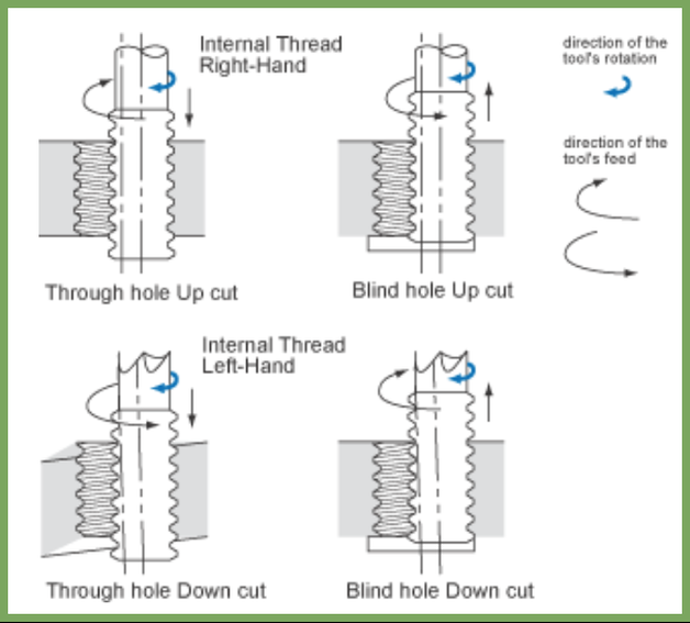
Understanding Thread Mills

Helical Interpolation Thread milling OSG Next Generation Tooling
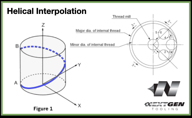
Figure 1. Helical Interpolation
Any three axis mill that is capable of helical interpolation can be used for thread milling. Helical interpolation involves three axes moving simultaneously. Two axes, 'X' and 'Y', move in a circular motion while the 'Z' axis moves in a linear motion.
​For example, the path from point A to point B (Figure 1) on the periphery of the cylinder combines a circular movement in the 'X-Y' plane with linear movement along the 'Z' axis. The 'X' and 'Y' circular motion will determine the diameter of the thread. The 'Z' axis linear motion will cut the pitch (or lead) of the thread.
Thread mills must completely enter the minor thread diameter before cutting the internal thread. (Figure 2)

Most all thread milling manufacturers' catalog lists the smallest internal thread that each thread mill can produce.

The same thread mill can also produce any larger size thread of that same pitch. Also, for small sizes, it is best to use our short series with the reduced length of cut whenever possible.
NPT threads are usually produced while interpolating the tool in a downward direction. Since these tools are crest cutting, it is not absolutely necessary to ream the internal minor diameter or mill the external diameter to size.
Figure 2. Thread mills must completely enter the minor thread diameter before cutting the internal thread.
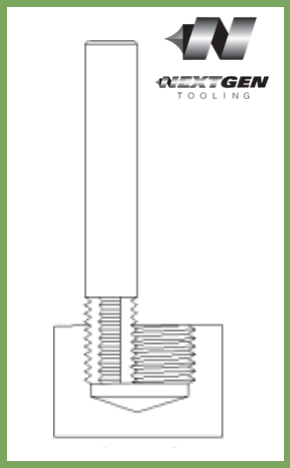
All of the straight flute thread mills are for internal threads only. All of the staggered tooth thread mills will cut both the internal and external threads. The helical thread mills over 0.187 diameter will also cut both internal and external threads.

Staggered tooth thread mills have every other tooth removed in a staggered pattern; as the tool rotates the adjacent flute fills in for the tooth that was removed. This helps to reduce side cutting pressure, thus reducing chatter. This can be extremely beneficial in small external sizes and for set-ups that lack rigidity.

Helical fluted thread mills are also designed to reduce side cutting pressure by distributing the cutting pressure along a helical flute. Although these tools cost slightly more, their high performance design allows for less chatter and higher feed rates.

How to Use Thread Mills

To produce internal threads, drill the minor thread diameter to its appropriate size. Then, position the thread mill to the required depth. Next, mill either the 'X' or 'Y' axis to the required thread pitch diameter. With small sizes and with difficult to cut material, it may be necessary to remove the material in several passes. It is always best to "arc-in" and "arc-out" when thread milling.

Any "arc-in" and "arc-out" movements must have a corresponding 'Z'-axis motion during the 'X-Y' circular moves. For example, if the "arc-in" is over 90 degrees, the 'Z'-axis departure must be 1/4 of the thread pitch. (90 degrees is 1/4 of a circle).
  • A right-hand thread is produced by orbiting in a counterclockwise direction while bringing the 'Z'-axis up one pitch per 360 degrees.
  • A left-hand thread is produced by orbiting in a clockwise direction while bringing the 'Z' axis up one pitch per 360 degrees.

The entire process can be achieved by interpolating in a downward direction and reversing the orbit direction.
However, it is highly advisable to do so since the tools will have much less material to remove. If the tool is to be interpolated in an upward direction, spiral interpolation must be used.

The same surface feet per minute can be used for thread mills as for end mills of the same size. The feed rate must be slower, however, since thread milling often involves unfavorable length-to-diameter ratios. Also, keep in mind that the thread mills have more surface area contact than an end mill of equal length. Most CNC mills are programmed in inches per minute which is applied at the centerline of the spindle.

In internal applications, the outside diameter of the tool will be traveling faster than the centerline of the tool. The reverse is true for external applications. It is best to start out conservatively with feed rates and the number of passes required and adjust upward per good machining practice.

External threads (Figure 3) must have the major diameter milled to size before the thread mill is used. Right-hand threads are cut by interpolating up and in a counterclockwise direction. The same threads can be cut by interpolating down and changing the orbit direction.

​NPT threads are usually produced while interpolating the tool in a downward direction. Since these tools are crest cutting, it is not absolutely necessary to ream the internal minor diameter or mill the external diameter to size.
Thread milling External boss Nect Generation Tooling OSG Tap Die
Figure 3. External Thread Milling

Troubleshooting Threadmilling

update August 2020:  OSG just released this new troubleshooting video that   further details some thread milling concepts.
2 Comments

Tap Troubleshooting

12/15/2010

0 Comments

 
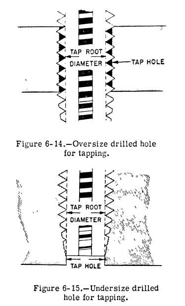
Troubleshooting problems with new taps.
Taps are very free cutting and will easily cut oversize threads if overfed or pushed. For the best results use a Tap Holder with built-in tension, compression.

Always utilize your holder's tension feature by programming spindle feed to 95-98% of the calculated feed rate.

Most drill size charts are based on using standard job drills which can drill over size by approximately .003". The charts are based on .003" over size condition to achieve the proper percentages of thread.
Picture
With today’s high precision drills, they are now capable of drilling to near net size. When using a high precision drill or a “G” drill you should refer to the drill size formula’s in the “Tapping Formulas” section of the catalog.
  • Tapped holes deeper than 1.5 diameters often call for a larger tap drill. 
  • Blind holes often require larger tap drills to reduce loads on the tap caused by chip build up in the hole.
  • Materials that tend to gall when tapped or when fasteners are installed should have larger drilled holes.
    Under tapping pressure, soft materials tend to extrude and enter the root area, necessitating a larger drilled hole.
  • Materials that don’t readily dissipate heat, should have larger holes to reduce the tooth contact area and minimize heat build up.
  • When making threads with high helix angles using a larger tap drill will help reduce tap breakage. 
Problem: Tapping oversized threads (no-go gage too loose)
Possible Cause Possible Remedy
Improper tap for material and thread application. · Use a suitable tap for the hole style and material being tapped. 
Cutting speed to high. · Reduce cutting speed.
· Improve coolant/lubrication.
Cold welding on the flanks of the tap (loading). · Use a new tool.
· Use surface treated taps.
· Improve coolant/lubrication.
· Grind away chipped and damaged teeth.
Chip packing in flutes. · Use tap with different flute geometry/angle.
· Possibly use set of taps.
Grinding burr. · Remove burr with soft wire or fiber brush.
Incorrect fixturing or positioning of part. · Use tap holders with axial and parallel floating.
· Check clamping of part for correct alignment.
Inconsistent feed of tap. · Tap with controlled feed.
· Check CNC programs.
· Check lead screw for backlash.
· Use compensating tension/compression tap holder.
Problem: Tapping oversized threads (no-go gage loose)
Possible Cause Possible Remedy
Tap selected too large for class of thread fit required. · Review markings on tap and determine if it is suitable for the class of fit required.
· If in doubt, contact us!
Improper reconditioning of tap. · Reconditioning of tap requires that all ground surfaces maintain the original geometry put on by the manufacturer.
Problem: Tapping bellmouthed hole (first few threads gage oversize)
Possible Cause Possible Remedy
Wrong initial starting pressure. · Work with controlled tap feed.
Axially hard working spindle. · Use a tap holder with length compensation.
Incorrect fixturing or positioning of part. · Use a tap holder with axial and parallel floating.
· Check clamping of part for correct alignment.
Problem: Torn and rough threads
Possible Cause Possible Remedy
Improper selection of tap for material and thread application. · Use a suitable tap for the hole style and material being tapped. 
Cutting speed too fast or slow. · Select proper cutting speed.
· Improve coolant selection to assist the effects of tap speed.
Cold welding on the flanks of the tap (loading). · Use a new tool.
· Use surface treated taps.
· Improve coolant/ lubrication.
· Find away chipped and damaged teeth.
Chips packing in flutes. · Use tap with different flute geometry/angle.
· Use set of taps.
Grinding burr. · Remove burr with soft wire or brush.
Tap drill too small. · Use correct size drill.
· If in doubt, contact us!
Insufficient coolant/ lubrication. · Selection of suitable coolant/lubrication for material being tapped.
· Use adequate amounts of coolant lubrication.
Tool overloading due to coarse pitch, hard materials or short chamfers. · Use a set of taps.
Problem: Tapping undersized threads (go gage won't enter/binds up part way into hole)
Possible Cause Possible Remedy
Tap selected too small to do multiple regrinds. · Limit the number of regrinds a tap has.
· Use a new tap.
Area of wear not removed when tap was resharpened. · Grind tap again.
· Use a new tap.
Improper tap for material and thread application. · Use suitable tap for the hole style and material being tapped.
Go gage binds up part way into hole. · Tap is dull - recondition or replace tap.
· Avoid too much axial force during tapping operation (this caused the tap to cut out of lead)
· Use tap holders with length compensation.
Tap selected too small for class of thread fit required. · Review markings on tap and determine if it is suitable for class of fit required.
Problem: Tap life too low
Possible Cause Possible Remedy
All reasons stated in torn and rough threads. · See torn and rough threads.
Loss of tap hardness by excess hear during regrinding. · Change the specification of the grinding wheel.
· Use coolant while grinding.
Loss of surface treatment from regrinding. · Retreatment of the tap surface.
· Check suitability of surface treatment for material being tapped.
Work hardened drill hole and hole chamfer. · Change or regrind tap drill more frequently.
· Check proper drilling speed and feed.
· Anneal part before tapping.
Problem: Torn and rough threads
Possible Cause Possible Remedy
Improper selection of tap for material and threading application. · Use a suitable tap for the hole style and material being tapped.
Tap drill too small. · Use correct size drill. Note that cutting and roll form taps use different size tap drills for same size thread.
Tap hole not deep enough. · Check actual drill depth, drill may have slipped back into holder.
Missing tap drill hole. · Ensure tap drill hole is present. Common problem in multiple spindle applications on transfer lines.
Chips packing in flutes. · Use tap with different flute geometry/angle.
· Use a set of taps.
Cutting speed too high or low. · Select proper cutting speed.
· Improve coolant/lubrication to assist the effects of the tap speed.
Cold welding on the flanks of the tap (loading). · Use a new tool.
· Use surface treated taps.
· Improve coolant/lubrication.
· Grind away chipped and damaged teeth.
Overload of the chamfer teeth. · Use longer chamfer.
· Increase number of tap flutes to provide more chamfered teeth.
Incorrect fixturing or positioning of part. · Use tap holders with axial/parallel floating.
· Check clamping of part for correct alignment.
Tap hitting the bottom of hole. · Use tap holder with length compensation and torque overload system.
Tapping hard or high tensile materials. · Check selection of tap, carbide tap may be more suitable then high speed steel taps.
0 Comments

    Technical Support Blog

    At Next Generation Tool we often run into many of the same technical questions from different customers. This section should answer many of your most common questions.

    We set up this special blog for the most commonly asked questions and machinist data tables for your easy reference.

    If you've got a question that's not answered here, then just send us a quick note via email or reach one of us on our CONTACTS page here on the website
    email us

    Authorship

    Our technical section is written by several different people. Sometimes, it's from our team here at Next Generation Tooling & at other times it's by one of the innovative manufacturer's we represent in California and Nevada.

    Archives

    March 2023
    February 2023
    January 2023
    December 2022
    November 2022
    October 2022
    September 2022
    August 2022
    July 2022
    June 2022
    May 2022
    April 2022
    March 2022
    February 2022
    December 2021
    November 2021
    October 2021
    September 2021
    August 2021
    July 2021
    June 2021
    May 2021
    April 2021
    March 2021
    February 2021
    January 2021
    December 2020
    November 2020
    October 2020
    September 2020
    August 2020
    July 2020
    June 2020
    May 2020
    March 2020
    February 2020
    January 2020
    September 2019
    August 2019
    July 2019
    June 2019
    May 2019
    March 2019
    January 2019
    September 2018
    June 2018
    April 2018
    February 2018
    December 2017
    November 2017
    October 2017
    August 2017
    June 2017
    April 2017
    March 2017
    February 2017
    January 2017
    December 2016
    November 2016
    October 2016
    August 2016
    March 2016
    February 2016
    January 2016
    November 2015
    August 2015
    July 2015
    May 2015
    April 2015
    March 2015
    November 2014
    August 2014
    July 2014
    December 2013
    November 2013
    September 2013
    July 2013
    March 2013
    December 2012
    March 2012
    November 2011
    May 2011
    March 2011
    January 2011
    December 2010
    November 2010
    October 2010

    Categories

    All
    5th Axis
    Aerospace
    Allied Machine
    Aluminum Oxide
    Angle Head
    AT3
    Balance
    Bellmouthed Hole
    Big Daishowa
    Big EWA Automatic Boring
    Big Kaiser
    BIG Plus
    Blue Photon
    Bone Screws
    Boring Tool
    Carbide
    Carmex Precision
    CBN
    Centerline Deviation
    Ceramic Black
    Ceramic End Mill
    Ceramic Inserts
    Ceramic Oxide
    Ceramic Whiskered
    Ceramic White
    Chamfer
    Champion Tool Storage
    Chip Breaking
    Circular Saw
    Class Of Fit
    CNC Lathe Tooling
    Collet
    Collet Chuck
    Collet ER
    Composites
    Covid-19
    Deep Hole Boring
    Deep Hole Drilling
    Drilling
    Dual Contact
    Dyna Contact Gage
    Dyna Force Tool
    Dyna Test Bar
    EMO
    End Mill
    Exotap
    Facemill
    Fixturing
    Fretting
    Gaylee Saw
    Hard Turning
    Heimatec
    Helical Interpolation
    Hohl Shaft Kegel
    How Its Made
    HSK A
    HSK-A
    HSK E
    HSK-E
    HSK F
    HSK-F
    HXL Tap
    Hy Pro Tap
    Hy-Pro Tap
    IMTS
    Jergens
    Kurt
    Lang
    Live Tooling
    MA Ford
    Maintenance Cart
    Mapal
    Martindale Saw
    Material: Aluminum
    Material: CFRP
    Material: D2
    Material: Hastelloy
    Material: Inconel
    Material: Peek
    Material: Stone
    Material Titanium
    Material: VC-10
    Metric Course Thread
    Metric Fine Thread
    Metric Thread Chart
    Microconic
    Micromachining
    ModLoc
    Modular
    Mogul Bars
    MPower
    No Go Too Loose
    NTK
    NTK HX5
    On Site Training
    OptiMill-SPM
    OSG Tap & Die
    Oversized Thread
    Parlec
    PCD
    PCT Firm Hold
    Platinum Tooling
    Projection Length
    Pull Studs
    Reamer
    Retention Knob
    Rotary Toolholders
    Rotary Toolholders BT
    Rotary Toolholders CAT
    Rotary Toolholders HSK
    Rotary Toolholders Hydraulic
    Rotary Toolholders Shrink
    Rough Thread
    Runout
    Runout Axial
    Runout Radial
    Saw Selection
    Short Tap Life
    Sialons
    Silicon Nitride
    Smart Damper
    Speed Increaser
    SpeedLoc
    Speroni STP Essntia
    Spindle Mouth Wear
    Swiss
    Swiss Machining
    Taper Wear
    Tapping Feed
    Tapping; Form
    Tapping IPM
    Tapping: Roll
    Tapping RPM
    Tapping Speed
    Tap Tolerance
    Technical Training
    Technicrafts
    Techniks USA
    Thread Milling
    Thread Whirling
    T.I.R.
    Tolerance
    Toolchanger Alignment
    Toolholder Taper
    Tool Presetter
    Torn Thread
    Troubleshooting
    UNC Thread Size
    Undersized Thread
    UNF Thread Size
    Unilock
    Vises
    Workholding

    RSS Feed

Picture

About
Contact
TOOLING
WORKHOLDING
EVENTS
NEWS
TECHNICAL


Established 1995
​

Next Generation Tooling
10240 Cavalletti Drive
Sacramento CA 95829
916.765.4227
Northern California
23 Maxwell Street
Suite B
Lodi, CA 95240
Southern California
22343 La Palma Avenue
​Suite 126
Yorba Linda, CA 92887
© 2023 Next Generation Tooling, LLC. 
All Rights Reserved
Created by Rapid Production Marketing

Find us on Instagram @nextgentool

  • Home
    • Schedule
    • Training
  • About
    • History
    • Contact
  • Territories
    • NorCal & N-NV
    • SoCal & S-NV
    • Mountains
  • Principals
    • Tooling >
      • 2V Industries
      • BIG Daishowa
      • Champion Storage
      • Drill America
      • Jewell Group
      • Mapal
      • Martindale Gaylee
      • OSG Tool
      • Performance Micro Tool
      • Platinum Tooling
      • TechniksUSA
    • Workholding >
      • BIG Daishowa
      • Earth Chain
      • Jergens
      • mPower Workholding
  • Promotions
  • Events
  • News
  • Technical