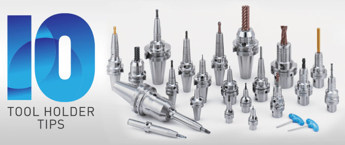
 The four critical requirements for tool holders are clamping force, concentricity, rigidity, and balance for high-spindle speeds. When these factors are dialed in just right, there’s nearly no chance of holder error and considerable cost reduction is achieved thanks to longer tool life and reduction of down-time due to tool changes. Easier said than done, our experts shared some of their best, quick-hitting advice for top tool holder performance in different situations. 1. Balance holders as a complete assembly Long-reach milling has some unique demands; when setting up this type of job, always balance tool holders as a complete assembly. While many tooling providers pre-balance their holders at the factory, it’s often inadequate, especially for long-reach applications. 2. Holder damage can go from bad to worse quickly Wear and tear on holders can be costly in the end, but there are ways to protect against it. Inspect and care for your holders. Trauma on a holder or spindle—dings, scratches, gouges, etc.—can magnify quickly. One bad holder can spread its problems like an illness. If you’re seeing disruptions like these on your holders, get them out of the rotation. 3. The rule of thumb on holder dimensions Looking for affordable ways to avoid vibration? Start by opting for a holder with a combination of the largest diameter and shortest length possible. 4. Rigidity can harm tapping operations What many don’t realize about tapping operations is that a perceived strength of collet chucks—their rigidity—can actually be detrimental. Rigidity does very little to counteract the dramatic thrust loads imposed on the tap and part, exacerbating the already difficult challenge of weathering the stop/reverse and maintaining synchronization. 5. Balancing is crucial to five-axis machining Five-axis machining introduces a whole new set of tooling challenges. While important in any type of machine, balance may be of most importance in full five-axis work. A well-balanced holder helps ensure the cutting edge of the end mill must be consistently engaged with the material in order to prevent chatter and poor surface finish quality. 6. Consider spindle speed requirements when choosing between shrink-fit and hydraulic holders If you have to choose between shrink-fit and hydraulic holders in a long-reach application, consider the spindle speed required. If a hydraulic chuck exceeds its rated RPM, fluid is pulled away from the holder’s internal gripping gland, causing loss of clamping force. But when used within its recommended operating range, a hydraulic tool holder offers superior runout and repeatability. On average, a good shrink-fit holder has about 0.0003-inch runout, while a hydraulic chuck offers 0.0001 inch or better. 7. Don’t overlook the tool’s effect on holder performance The cutting tool affects holding ability more than most machinists and engineers realize:
8. Not all dual-contact tooling is the same Anyone in the market for BIG-PLUS dual-contact tooling should consider this simple statement: Only a licensed supplier of BIG-PLUS has master gages that are traceable to the BIG grand master gages and have the dimensions and tolerances provided to make holders right. Everyone else is guessing and using a sample BIG-PLUS tool holder as their own master gage—a practice that any quality expert will advise against. Look for the marking: “BIG-PLUS Spindle System-License BIG DAISHOWA SEIKI.” 9. You may have a BIG-PLUS spindle and not even know it You’d be surprised how often we hear from our certified regrinders or engineers in the field about folks that didn’t realize their machine had a BIG-PLUS spindle—the message can get lost in the supply chain or during the sales process. The easiest way to know if an interface is BIG-PLUS is to place a standard tool into the spindle and see how much of a gap there is between the tool holder flange face and spindle face. Without BIG-PLUS, the standard gap should be visible, or about 0.12 in. If it is BIG-PLUS, the gap is half of this amount, or only 0.06 in. These values change depending on 30 taper, 40 taper or 50 taper sizes, but the gap is visibly less than usual. 10. Use positive offsets during holder setup It may be how it’s traditionally been done but touching off holder assemblies in each machine to establish negative tool offsets based on the zero-point surface—the vise, machine table, workpiece, etc.—is not the most efficient process. We think the choice is pretty clear: adapting machines to a single presetter so they can receive positive gage lengths is superior to using all types of machine-specific negative offsets.
This is a change to “the way things have always been done” that can be met with some resistance, but in the grand scheme of things, it’s a relatively small and simple step that makes life much easier. It’s a relatively low-cost opportunity to introduce more standardization of holder setup to the shop floor. Holders are the bridge between the machine and the part. That’s a lot of pressure—literally and figuratively. It’s important to select, care for and use holders carefully from the day they are purchased until they’re tossed into the recycling bin. From collet chucks to coolant inducers, BIG KAISER is North America’s source for standard-bearing tool holders that guarantees high performance. Explore the full lineup.
0 Comments
We are very excited to announce that we are now able to offer on-site technical training to YOUR machinists at YOUR location! This is offered at no charge to customers who use any of the manufacturer's whom we represent in California and Nevada. However, just because you don't purchase things from us, don't feel left out! We also offer on-site topic specter training on any of the following topics for $150/hour. Each presentation lasts about 2 hours. The presentations last approximately 45-60 minutes with the remaining time for Q&A and discussion about unique applications in your facility.  Training Classes Available: Machining 101
Advanced Part Manufacturing:
NTK's industry leading line of ceramic cutting tools recently expanded with new solid CERAMIC end mills! You can see our product announcement here: NTK now offers SX9 Ceramic End Mills for Cutting Exotic Alloys which contains the various features. Below is the technical info on how to run the NTK Ceramic End mills and a troubleshooting guide. NTK's SX9 cermaic end mill grade can run at speeds of 2000 SFM. The line-up includes 4 and 6 flutes in inch and metric versions. Again, you can learn more about on our Blog Post. Solid ceramic end mills are made with SX9 SiAlON grade substrate which features a balance of toughness and wear resistance. It's suitable for even the most demanding applications. 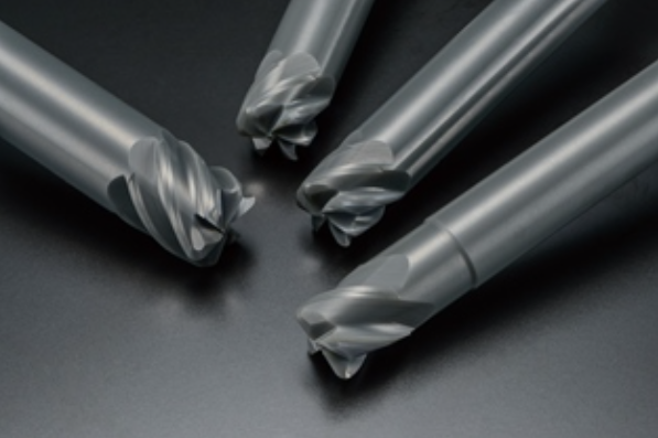 NTK Ceramic end mills with SX9 SiAlON substrate First Step Machining Procedures
Gernarel Recomendations for machining heat resistant alloys & PH stainless steel
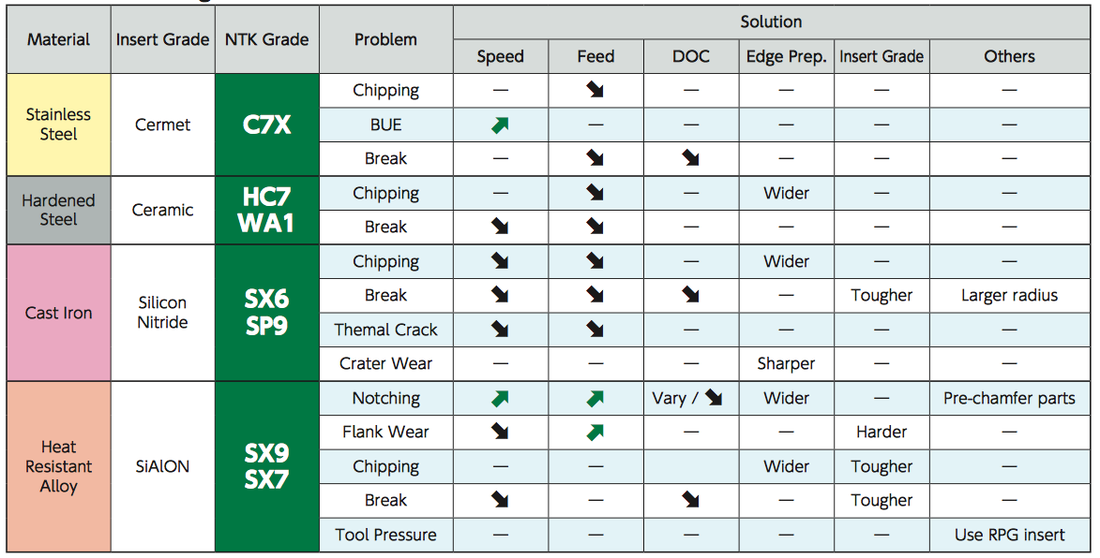 NTK Ceramic end mills Troubleshooting guide As with any other techncial questions please get in touch with us on our CONTACTS page and we can provide both over-the-phone troubleshooting or schedule at time for on-site techncial training.
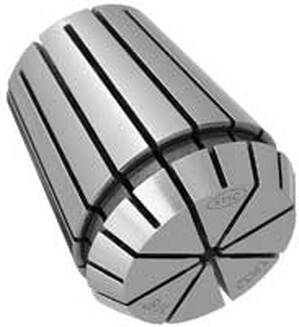
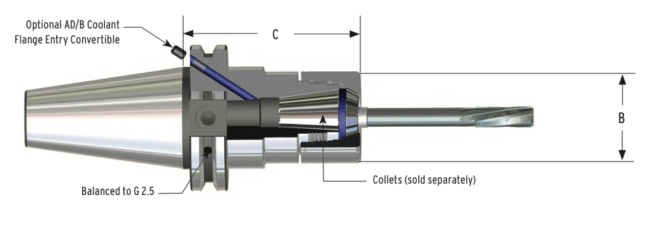 We often get asked to spec out tooling packages for new CNC mills and one of the questions we encounter most, or should, is how do you select the right toolholder collet size for your companies applications? The real choice is in the size of the collet chuck itself. So several considerations should be reviewed... What size are your tools?Your first consideration should be the size of end mills or drills you will be using most often. If you are doing smaller work you would require smaller diameter range collets. Generally you may prefer the ER16 and ER32 sizes. If you are doing very small work then perhaps an ER11 set would be the best choice. If the bulk of your tool requirements are in the mid range you can also use the ER20. The following is a list of tool diameters that can be used with each size collet chuck. Essentially, the most popular, and again, readily available from a number of sources, are the ER 16, ER20, and ER32... in no particular order.
If you need more detailed list of dimensions can be found at these links: 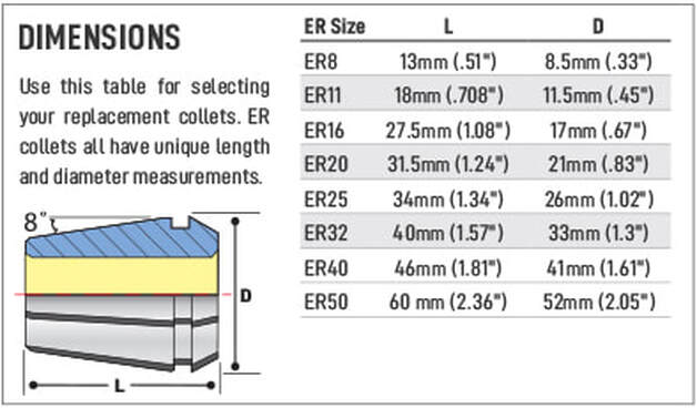 How far do you need to reach?A second consideration is the actual reach of the tool. Not projection reach, also know as “gage length” "l1" but projection diameter “D”. Obviously, stubbier is better for projection reach "L1". But, you also need to review the families of parts that you intend to run on the machine. If you intend to use the holder to "reach" into a tight fit then the OD of the projection "D" of the toolholder needs to be considered. Many shops don't always consider this and end up using much longer carbide shanked end mills to get into deep pockets when getting a smaller diameter ER collet and collet chuck would be much less expensive over the life of the job. 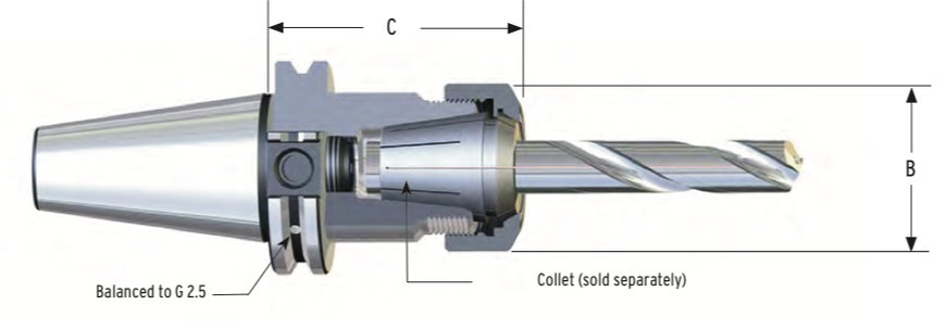 Here is a list of the OD projection diameters:
Sometimes there is just no getting around having a custom tool made. Get in contact with us if you just can't seem to reach into the part with your toolholder.  |
Technical Support BlogAt Next Generation Tool we often run into many of the same technical questions from different customers. This section should answer many of your most common questions.
We set up this special blog for the most commonly asked questions and machinist data tables for your easy reference. If you've got a question that's not answered here, then just send us a quick note via email or reach one of us on our CONTACTS page here on the website. AuthorshipOur technical section is written by several different people. Sometimes, it's from our team here at Next Generation Tooling & at other times it's by one of the innovative manufacturer's we represent in California and Nevada. Archives
July 2024
Categories
All
|
 RSS Feed

About
|
© 2024 Next Generation Tooling, LLC.
All Rights Reserved Created by Rapid Production Marketing
|
