|
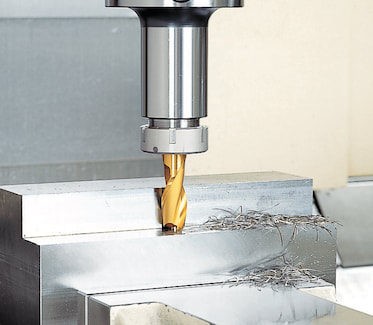
by Bernard Martin There have been some who claim that drawbar gripper fingers and/or ball marks that appear on retention knob head after several tool changes is normal. 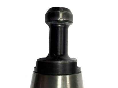 It is NOT.
THAT IS FALSE. According to Haas CNC, ball or gripper marks on the edge of the pull stud indicate that the drawbar does not open completely. If you see these indication marks you should check your drawbar and replace these pull studs immediately.
0 Comments
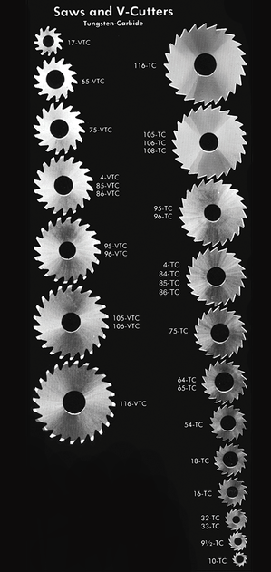
compiled & edited by Bernard Martin 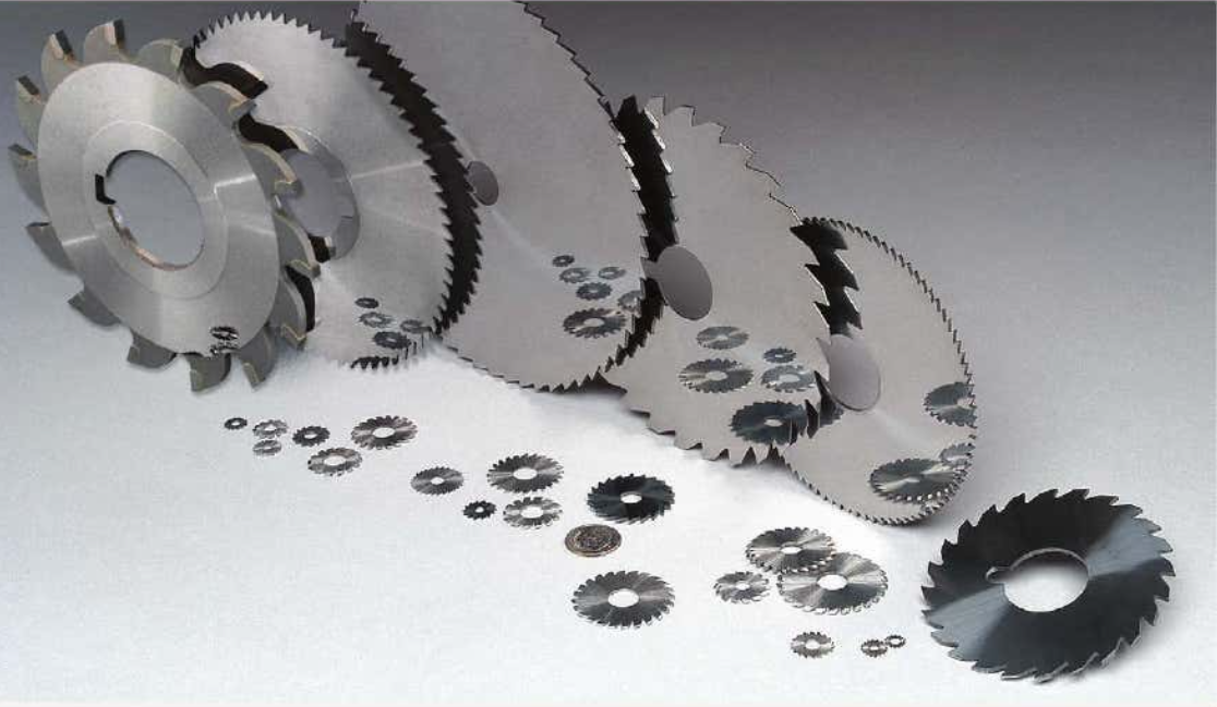 As more and more of our customers are using Martindale Gaylee Circular saws we put together this guide to the commonly asked questions such as "Is there a rule-of-thumb for the number of teeth?" or "How much side clearance should I have?" Here we cover a lot of the fundamentals of selecting the right circular saw blade configuration, some tips, tricks, and troubleshooting for when things go wrong. Circular Saw Feed RatesThese are general cutting speed recommendations for circular saws used in metalcutting from Martindale/Gaylee. The may vary from application to application but are basically some general suggestions starting parameters when using high speed or carbide saws.
Selecting the Proper Number of Teeth in Your Metalcutting SawGenerally speaking, deep cuts and soft material require fewer teeth for chip clearance and stronger teeth (landed). Thin material requires more teeth, but keep-in-mind that at least 2 teeth on the blade need to be engaged in cut. Hard materials and narrow slots (under .025”) likewise require more teeth. Hard Materials require more teeth, and give a smoother cut, but at a much lower production rate. Alternately beveled teeth keep chips from sticking in the cut and in the tooth gullets. And Remember that there should be at least 2 teeth engaged in the cut at all times.
Rake Angles and Side Clearance AnglesRAKE ANGLES Just as in an end mill or a band saw blade, a rake angle is the term used to describe the direction of the blade’s teeth, as referenced from the rotation and central axis of a saw blade. If you imagine a line going from the exact center of the blade to each tooth, having the front of the tooth directly on that line would be a zero degree rake angle. The rake angle of the blade is described in comparison to that imaginary line. A positive rake angle meana that the teeth are angled more towards the angle of rotation, while a negative rake angle would mean that they are angled backwards, away from the direction of rotation. Generally speaking, the preferred rake angle is:
SIDE CLEARANCE (Tangential Clearance Angle) This is also known as dish or hollow grind. You measure down the side of the tip and the difference it is the difference between front and back. As you cut, material it gets compressed and springs back after the cutting edge passes. A steep side clearance angle gives plenty of room for the material to expand and prevents thermal expansion of the base material. Keep in mint that a very flat side clearance angle can provide a smoother cut in some materials. For stainless steel and tenacious metals such as copper, zinc, tin or lead an increase in the side clearance is desirable as these materials tend to "spring back" (thermal expansion) on the blade.  It’s time for machine tool builders and machining companies to shelf the long-standing ISO 1940-1 standard in favor of ISO 16084:2017. Not only is balancing tools rarely necessary, it can also be risky. A lot of conflicting information has circulated over the years about balancing tools. As an author of the new standard for calculating permissible static and dynamic residual unbalances of rotating single tools and tool systems – ISO 16084:2017 – allow me to clear some things up and, hopefully, make life a little easier for you.
Since its institution in 1940, the G2.5 balance specification has been widely accepted across the industry; i.e., “it’s how things have always been done.” However, machines were much slower 80 years ago. Back then, the most advanced machines would have spun larger, heavier tools at a maximum speed of about 4,000 RPM. If you applied the math from those days to today, you’d get unachievable values. For example, the tolerances defined by G2.5 for tools with a mass of less than 1 pound rated for 40,000 RPM calculates to 0.2 gram millimeters (gm.mm.) of permissible unbalance and eccentricity of 0.6 micron. This isn’t within the repeatable range for any balance machine on the market. Similarly, application-specific assemblies, for operations like back boring and small, lightweight, high-speed toolholders, can’t be accurately balanced for G2.5. Machine tool builders rely on an outdated number, too, often basing spindle warranty coverage on using balanced tools at very specific close tolerances. While it’s true that poorly balanced tools run at high speeds wear a spindle faster, decently balanced tools performing common operations won’t wear spindles or tools drastically and deliver the results you’re looking for. While it’s true that poorly balanced tools run at high speeds wear a spindle faster, decently balanced tools performing common operations won’t wear spindles or tools drastically and deliver the results you’re looking for. A Little Lesson About ForcesThis all begs the question: When do you need to take the time to balance holders? I would argue that tools require balancing only if they’re notably asymmetrical or being used for high-speed fine finishing. Here’s a rule I’ve long followed: If cutting forces exceed centrifugal forces due to unbalance, high-precision balancing isn’t needed because the force required to balance the tool will most likely be less than cutting forces.
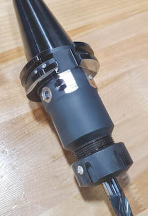
At that point, aggressive cutting – not unbalance – is going to damage the spindle. Unbalanced tools are also blamed for issues that turn out to be misunderstandings about a machine’s spindle. I’ve visited shops with new high-speed spindles that had trouble running micro tools over 15,000 RPM. They rebalanced all the tools on the advice of their machine tool supplier, but to no avail. It turned out the machine was tuned for higher torque and higher cutting forces. Before going to the effort of balancing toolholders, work with your machine builder to understand where a spindle is tuned. Not only is balancing tools rarely necessary, it can also be risky. Our inherently asymmetrical fine-boring heads are a good example. Because we balance them at the center, a neutral position of the work range, you lose that balance if you adjust out or in. To adjust, you’d typically add weight to the light side, which can be a problem for chip evacuation and an obstructor. Or you can remove weight from the heavy side, but that means you have to put some big cuts on the same axis of the insert and insert holder, ultimately weakening the tool. In longer tool assemblies, common corrections made for static unbalance can also cause issues. It happens when a toolholder is corrected for static unbalance in the wrong plane; i.e., adding or removing weight somewhere on the assembly that’s not 180 degrees across from the area where there’s a surplus or deficit. Once the tool is spun at full speed, those weights pull in opposite directions and create a couple unbalance that often worsens the situation. 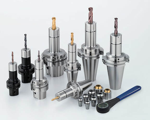 All the components of Big Kaiser's Mega ER Grip Series - Body, Collet and Collet nut - Are all balanced for high speed machining A Cautionary TaleIf you do go down the balancing road, you’d better know where you can modify tools, what’s inside, how deep you can go, and at what angles. Whether you’re adding or removing material on a holder, I highly recommend consulting the tool manufacturer for guidance first. As a cautionary tale, consider a customer who was attempting to balance a batch of our coolant-fed holders. Based on the balancing machine, the operator drilled ¼-inch holes at the prescribed angle into the body of the holders. Not realizing what was inside, he drilled into cross holes connecting coolant flow and ruined several holders. Tooling manufacturers are doing their part to avert disasters like this. For most, simple tools like collet chucks or hydraulic chucks are fairly easy to balance during manufacturing. We account for any asymmetrical features while machining and grinding holders and pilot each moving part, ensuring they’ll locate concentrically during assembly. These measures ensure the residual unbalance of the assemblies is very, very low and eliminate the need for balancing.
Decades of the same standards have conditioned us to think a certain way about balancing tools. While it seems logical that every tool must be balanced, it’s just not the case: Many issues attributed to unbalance aren’t caused by unbalance, and the risks of balancing every single tool often aren’t worth the reward.
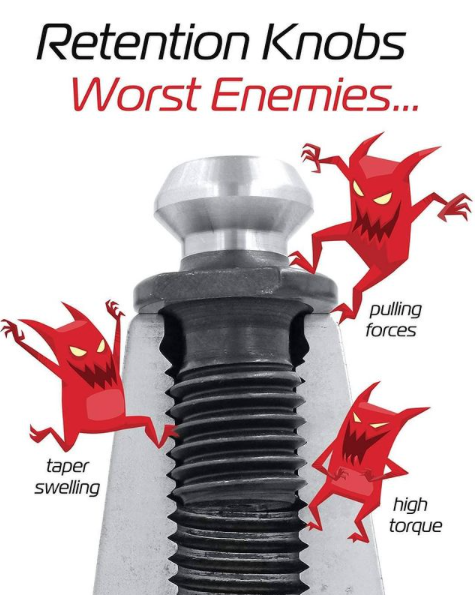
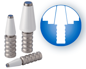
Save your balancing time and resources for high-speed fine finishing. If you do have work where balance is crucial, consider how the tools you buy are balanced and piloted out of the box and/or consult your partners before making any modifications. by Bernard Martin Retention Knobs are the critical connection between your machine tool and the tool holder and they are the only thing holding a steep taper tool holder in the machine’s spindle. Techniks has recently introduced their MegaFORCE retention knobs that have some rather unique features when compared to standard pull studs. Before delving into the features of the MegaFORCE pull studs, let's review some things that you may not know, or think about, on a daily basis.
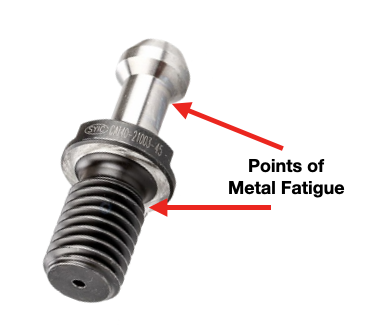
According to Haas, you should expect a service life of about 6000-8000 hours for a retention knob. Most all rotary toolholder manufacturers state that you should be replacing your pull studs at least every three years. However, if you're running multiple shifts, 24-7, making lots of tool changes, making very heavy cuts with long reach or heavy cutting tools, and/or have ball lock style grippers instead of collet type grippers used on the retention knob, you will probably need to replace your studs at least every six months. Given the spindle speeds that we are running at to remain competitive, retention knobs are not an item that you want to take a chance on breaking. I can tell you firsthand that 5 pound toolholder with a drill in it flying out of the spindle at 23,000 RPM is not something you want to experience. METAL FATIGUE: WHY THEY FAILPull studs encounter catastrophic failure as a result of metal fatigue. The metal fatigue can be caused by a number of reasons including poor choice of base material, engineering design, machining process, poor heat treatment, and, sometimes, they have just met or exceeded their service life. We're going to dig into each of these reasons below but first let's look at some threading fundamentals.
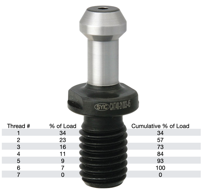
The load on each subsequent thread decreases from there, as show in the table. Any threads beyond the first six are purely cosmetic and provide no mechanical advantage. Additional threads beyond the sixth thread will not further distribute the load and will not make the connection any stronger. That is why the length of engagement of the thread on a pull stud is generally limited to approximately one to one & a half nominal diameter. After that, there is no appreciable increase in strength. Once the applied load has exceeded the first thread's capacity, it will fail and subsequently cause the remaining threads to fail in succession. RETENTION KNOB DESIGNRepetitive cycles of loading and unloading subject the retention knob to stress that can cause fatigue and cracking at weak areas of the pull stud. What are the weak areas of a standard retention knob?
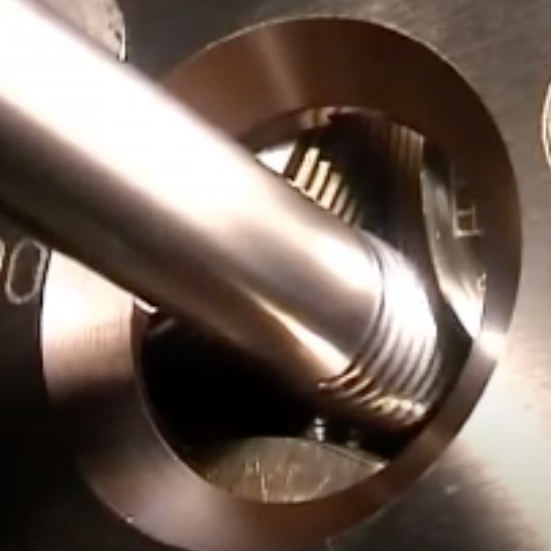
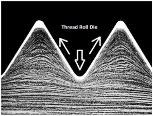
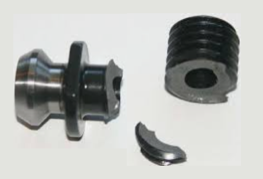
The most common failure point for a retention knob is at the top of the first thread and the underside of the pull stud where the grippers or ball bearings of the drawbar engage and draw the toolholder into the spindle. Remember, bigger Radii are stronger than sharp corners. More on that soon. 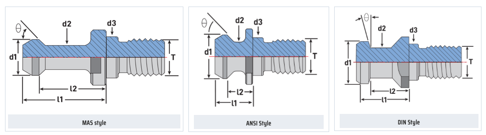 Styles of MegaFORCE Retention Knobs MATERIALNot all retention knobs are made from the same material, however, material alone does not make for a superior retention knob. Careful attention to design and manufacturing methods must be followed to avoid introducing potential areas of failure. Techniks MegaFORCE retention knobs are made from 8620H. AISI 8620 is a hardenable chromium, molybdenum, nickel low alloy steel often used for carburizing to develop a case-hardened part. This case-hardening will result in good wear characteristics. 8620 has high hardenability, no tempering brittleness, good weldability, little tendency to form a cold crack, good maintainability, and cold strain plasticity. There are some companies making retention knobs from 9310. The main difference is the lower carbon content in the 9310. 9310 has a tad more Chromium, while 8620 has a tad more nickel. Ultimate Tensile Strength (UTS) is the force at which a material will break. The UTS of 8620H is 650 Mpa (megapascals: a measure of force). The UTS of 9310H is 820 Mpa. So, 9310H does have a UTS that is 26% greater than 8620H. That said, Techniks chose 8620 as their material of choice because of the higher nickel content. Nickel tends to work harden more readily and age harden over time which brings the core hardness higher as the pull stud gets older. The work hardening property of 8620 makes it ideally suited for cold forming of threads on the MegaFORCE retention knobs. It should be noted that some companies are using H13. H13 shares 93% of their average alloy composition in common with 9310. ROLLED THREADS VS. CUT THREADS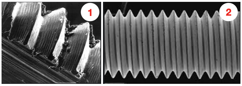 A cut thread, image 1, has a higher coefficient of friction due the the cutting process, while a roll formed thread, image 2, has a lower coefficient of friction which means that it engages deeper into the toolholder bore when subjected to the same torque. You will notice that Cutting threads tears at the material and creates small fractures that become points of weakness that can lead to failure. Rolled threads have burnished roots and crests that are smooth and absent of the fractures common in cut threads. Rolled threads produce a radiused root and crest of the thread and exhibit between a 40% and 300% increase in tensile strength over a cut thread. The Techniks MegaFORCE retention knobs feature rolled threads that improve the strength of the knob by 40%.
Also, unlike thread cutting, the grain structure of the material is displaced not removed.
By comparison, cut threads interrupt the grain flow creating weak points. MEGAFORCE GEOMETRIC DESIGN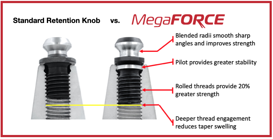 Overall Length There are some claims that a longer projection engages threads deeper in the tool holder preventing taper swelling. While a deeper thread engagement can help prevent taper swelling, applying proper torque to the retention knob is an effective way to reduce taper swelling. An over-tightened retention knob may still cause taper swelling regardless of how deep it engages the threads of the tool holder. Additionally, the longer undercut section above the threads presents a weak point in the retention knob.
Ground Pilot There is a ground pilot, underneath the flange, which provides greater stability. The pilot means the center line of the tool holder and pull stud are perfectly aligned. Magnetic Particle Tested Each Techniks MegaFORCE retention knob is magnetic particle tested to ensure material integrity and physical soundness. MegaFORCE retention knobs are tested at 2.5X the pulling forces of the drawbar.
RETENTION KNOB BEST PRACTICESIn order to maximize the life of your retention knob and prevent catastrophic failure here are some technical tips to keep your shop productive and safe.
Special thanks for Greg Webb at Techniks and Mike Roden from Fette Tools/ Turning Concepts, for providing technical insights.
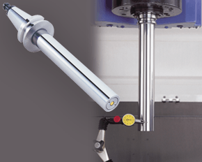
A machine’s spindle is one of the key links in the machining chain. In other words, if there are irregularities inside or at the face, they can show up on your part. It makes regular inspection and spindle maintenance critical to getting the most out of your equipment and maintain process efficiency. These three accessories, the Dyna Contact Taper Gage, the Dyna Test Bar and the Dyna Force Measurement Tool, can help you perform this maintenance easily without eating into valuable spindle time. Dyna Contact Taper Gage
Dyna Test Bar
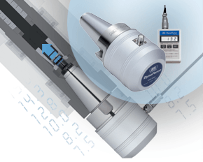
With the help of a dial indicator, you can uncover any runout while safely spinning the spindle at a very low RPM and verify the parallelism of Z-axis motion. Dyna Force Measurement Tool
The Dyna Force measurement tool provides a precise digital reading that reveals reduction in retention force in increments of 0.1kN. If you would like a demonstration for any of these tools contact us or set up an appointment for one of our Next Generation Tooling engineers to visit you!
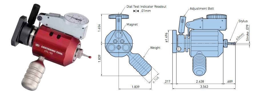 With this innovative centering tool from Big Kaiser, spindles and tools can be centered quickly and easily. It's ideal for limited spaces within small lathes. The Centering Tool is a static dial gauge for easy centering.
We are very excited to announce that we are now able to offer on-site technical training to YOUR machinists at YOUR location! This is offered at no charge to customers who use any of the manufacturer's whom we represent in California and Nevada. However, just because you don't purchase things from us, don't feel left out! We also offer on-site topic specter training on any of the following topics for $150/hour. Each presentation lasts about 2 hours. The presentations last approximately 45-60 minutes with the remaining time for Q&A and discussion about unique applications in your facility.  Training Classes Available: Machining 101
Advanced Part Manufacturing:
NTK's industry leading line of ceramic cutting tools recently expanded with new solid CERAMIC end mills! You can see our product announcement here: NTK now offers SX9 Ceramic End Mills for Cutting Exotic Alloys which contains the various features. Below is the technical info on how to run the NTK Ceramic End mills and a troubleshooting guide. NTK's SX9 cermaic end mill grade can run at speeds of 2000 SFM. The line-up includes 4 and 6 flutes in inch and metric versions. Again, you can learn more about on our Blog Post. Solid ceramic end mills are made with SX9 SiAlON grade substrate which features a balance of toughness and wear resistance. It's suitable for even the most demanding applications. 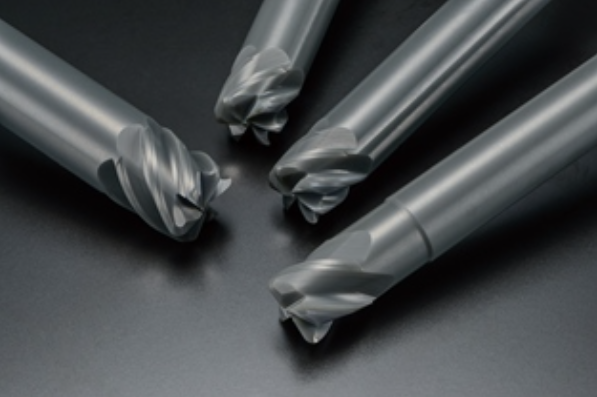 NTK Ceramic end mills with SX9 SiAlON substrate First Step Machining Procedures
Gernarel Recomendations for machining heat resistant alloys & PH stainless steel
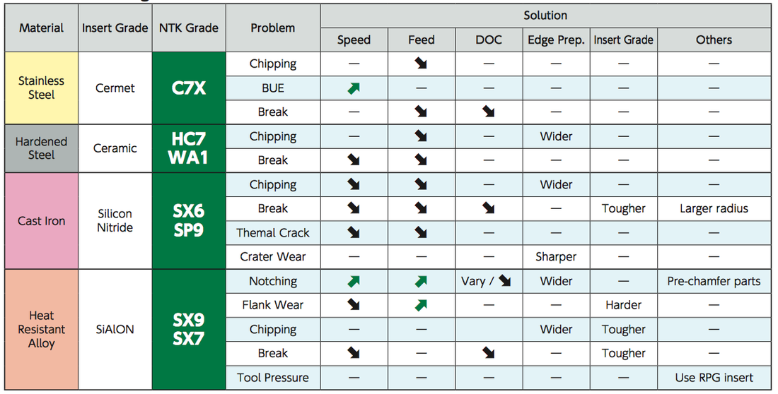 NTK Ceramic end mills Troubleshooting guide As with any other techncial questions please get in touch with us on our CONTACTS page and we can provide both over-the-phone troubleshooting or schedule at time for on-site techncial training.
|
Technical Support BlogAt Next Generation Tool we often run into many of the same technical questions from different customers. This section should answer many of your most common questions.
We set up this special blog for the most commonly asked questions and machinist data tables for your easy reference. If you've got a question that's not answered here, then just send us a quick note via email or reach one of us on our CONTACTS page here on the website. AuthorshipOur technical section is written by several different people. Sometimes, it's from our team here at Next Generation Tooling & at other times it's by one of the innovative manufacturer's we represent in California and Nevada. Archives
July 2024
Categories
All
|

 RSS Feed

About
|
© 2024 Next Generation Tooling, LLC.
All Rights Reserved Created by Rapid Production Marketing
|
