|
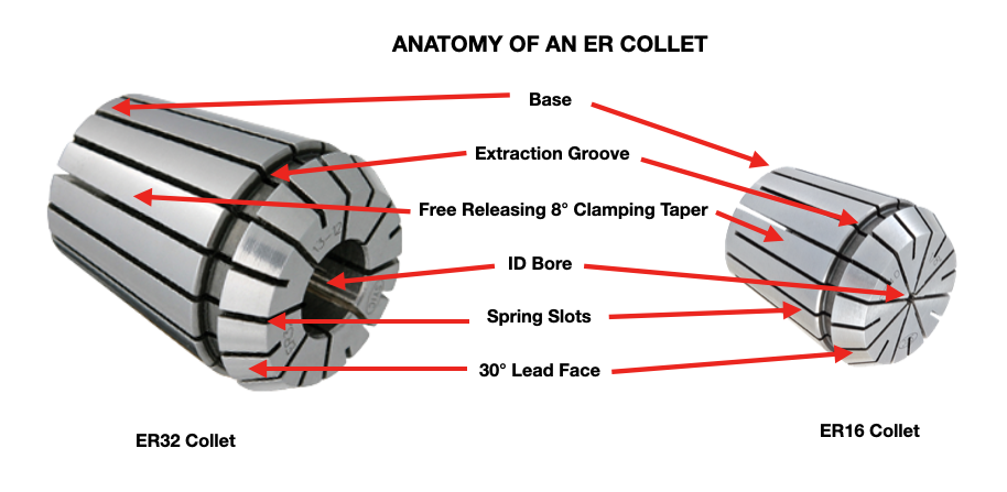
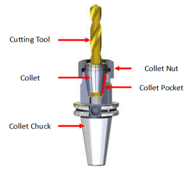
Edited by Bernard Martin If you work in the metalcutting, signmaking or cabinet making manufacturing industry, the term “collets” is already very familiar to you. There are many types of collets used in many different industries and applications. This article is focused on collets used in rotary tool holders found in CNC milling machining centers and CNC Routers and also used in CNC Lathes and Swiss Style CNC's. Let's cover the basics: What are Collets?Collets are the critical connection between the cutting tool and the tool holder, also called a collet chuck. Most collets are round, cone-shaped, and slotted. Collets encircle the cutting tool shank to evenly distribute holding power around its center bore. Before getting too deep into the technical aspect of collets, It's going to be helpful to anyone new to the use of collets to understand the basic anatomy of collets and of a collet chuck system. How Collets WorkThe tapered collet base is made to fit into the collet pocket of the collet chuck body. The free release locking tapered (16°included, 8° per side) design of the collet base and collet pocket allows the collet to be centered in the pocket as it is pushed in by the collet nut on the lead face during setup.
This centering effect enables the collet to achieve a high degree of accuracy (concentricity); much more than drill chucks and side-lock style end mill holders. As he collet nut is tightened down on the collet, it is pushed into the pocket collet chuck pocket. The slots in the collet allow the I.D. bore to collapse and apply clamping pressure to the cutting tool shank. It's essentially a spring that is compressed tight around the shank of the cutting tool such as a drill or end mill. The result is a very strong and rigid clamping force on the cutting tool. Since the collet base is tapered to match the collet pocket, tool runout (T.I.R.) is reduced. Total indicator runout (TIR) is a term often used in manufacturing, especially when dealing with rotating parts such as cutting tools, particularly endmills and drills. TIR is defined as the difference between the maximum and minimum values measured across an entire rotating surface about a reference axis.
0 Comments
|
Technical Support BlogAt Next Generation Tool we often run into many of the same technical questions from different customers. This section should answer many of your most common questions.
We set up this special blog for the most commonly asked questions and machinist data tables for your easy reference. If you've got a question that's not answered here, then just send us a quick note via email or reach one of us on our CONTACTS page here on the website. AuthorshipOur technical section is written by several different people. Sometimes, it's from our team here at Next Generation Tooling & at other times it's by one of the innovative manufacturer's we represent in California and Nevada. Archives
July 2024
Categories
All
|
About
|
© 2024 Next Generation Tooling, LLC.
All Rights Reserved Created by Rapid Production Marketing
|


 RSS Feed
