|
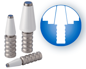
Written and edited by Bernard Martin PowerCOAT Collet Nuts provide up to a 75% increase in holding power! 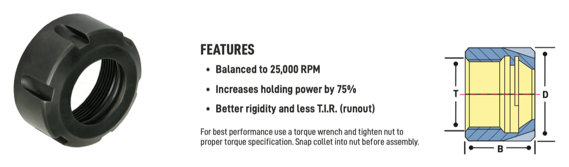 One of the most important elements of the toolholding 'system' is the collet nut. Each toolholder "system" consists of a precision ER tool holder that comes with a special "Power Coated" high power nut that holds tighter than any other nuts. According to Techniks, the 'Power Coat' nut is the secret to their high holding power. Because it holds so tight, the 'Power Coat' nut improves T.I.R., extends carbide tool life, and improves finish in heavy milling operations. Techniks recommends that for best results always tighten the nut to the proper torque using a torque wrench with a tightening stand, and never over-tighten the nut because this can damage both the collet and the collet pocket. To demonstrate the difference between an uncoated and coated collet nut, Mike Eneix, from Techniks did some testing. He took an uncoated, imported nut and put it to the test against the Parlec PowerCOAT nut. Mike took them to the limit to see which one gives you more holding power. Check out the video below! What makes the difference?As anyone knows who has changed a flat tire on their car, tightening down a nut on a 60 degree thread involves some friction as the mating metal surfaces interact. That's why nuts can be a bit 'hot' to the touch when you take them off. The objective with the "Power Coated" nuts was multifold:
First Techniks needed to reduce the coefficient of friction on the thread angle to enable more lubricity for the nut to tighten down farther. As we all know 'heat' causes metal to "grow" so what may at first appear to be tight, in fact, loosens, as soon as you stop tightening it. Second they needed to make sure that the front surface of the collet that engages the shorter 30 degree taper on the front of an ER collet did not 'twist' as the night tightened down. Both problems really involved reducing friction and through a combination of engineering tolerances and unique coating process we believe that we've found the most economical solution to eliminate the use of cheater bars and collet over torque. Here's what they've found out in testing the "Power Coated" Nuts:
“Power Coat” is an innovative, permanent coating that increases clamping pressure of the nut up to 75% compared to standard ER nuts. More holding power reduces the chance of spinning the shank of the tool inside the collet, which can cause premature failure of the collet.
1 Comment
A Swiss type CNC automatic lathe and a CNC lathe, they are similar lathe machines, but did you know they are completely different? In this article, the kind folks at NTK Cutting Tools will introduce the 4 differences between the cutting tools used based on the mechanical structure of Swiss CNC automatic lathes and CNC lathes. What is the difference between a “Swiss CNC Automatic Lathe” and a “CNC lathe”?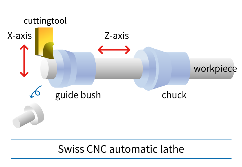
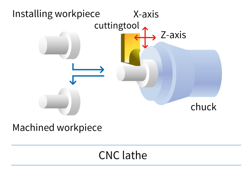
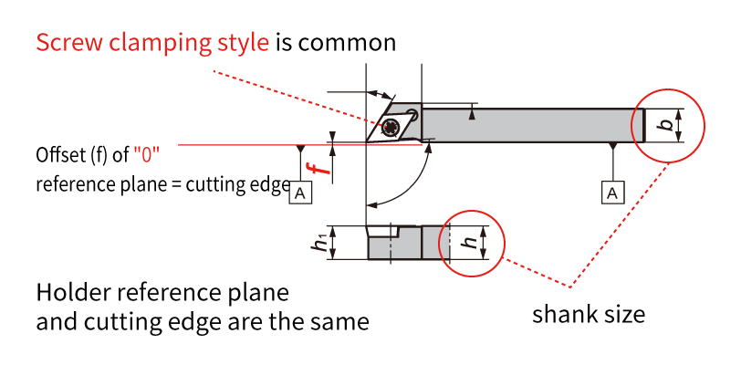
Swiss CNC automatic lathe & CNC lathe: Since the machine structure, workpiece, and size are different, it is important to select the cutting tool accordingly. Now let's take a look at the features of cutting tools used in CNC automatic lathes. Difference 1. HolderThe holder is an important component for achieving chip performance. I will explain the difference between the holder used on a Swiss type CNC automatic lathe and a CNC lathe.
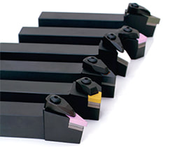
Holders for Swiss CNC Automatic Lathe
CNC Lathe Holders
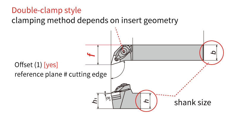
Difference 2. Insert geometry: Positive inserts and Negative insertsCNMG... DNMG...: If you are familiar with machining on CNC lathes, you likely know about insert geometries. The Swiss type CNC automatic lathe is the same type of lathe, but if you are thinking of machining with the same insert, be careful! Inserts such as "CNMG /CNGA..." and "DNMG/DNGA ..." used on CNC lathes have many corners, and the cutting edge is honed or chamfered (edge preparation) and have excellent cutting edge strength. These inserts are ideal for shearing the workpiece material. On the other hand, when a negative insert such as "CNMG/CNGA..." is used on a Swiss type CNC automatic lathe, cutting resistance tends to be high and "chatter" and "work deflection" occur. We recommend using a "positive style" for Swiss CNC automatic lathes. Swiss-type CNC automatic lathes machine workpieces that are smaller in diameter and require higher precision than machining on a CNC lathes. High cutting resistance causes “vibration” and “dimensional defects”, so using a “positive insert” with a relief angle to reduce cutting resistance and achieve stable machining. 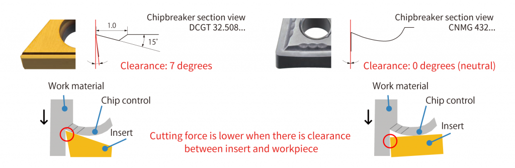 As shown above, the larger the clearance angle (relief), the smaller the area where the tool touches the workpiece. This reduces cutting resistance. b Difference 3. Insert tolerance: G-class and M-class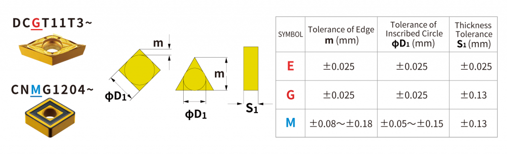 The ISO insert designation includes a tolerance class. I will discuss the difference in insert tolerance classes for Swiss type CNC automatic lathes and CNC lathes. The table above compares the “M” class commonly used on CNC lathes with the “G” class and “E” class commonly used on Swiss SNS automatic lathes. The 3rd letter in the insert part description identifies the tolerance class. Insert such as CNMG… and DNMG… have an M class tolerance. On the other hand, inserts such as DCGT… and CCGT… have a G-class tolerance. As shown in the table, the insert tolerance is very different between the “G” and “M” class. Corner length (m) and insert IC (dia. D1) tolerance affect the accuracy of the cutting edge position, or workpiece dimensions. Thickness tolerance (S1) affects the height of the cutting edge. Swiss-type CNC automatic lathes require high precision machining of small diameter workpieces, so “G-class” or “E-class” with higher tolerance than M-class are used. Also, the upper and lower insert surfaces of G-class and E-class inserts are polished and the outer edges are ground with high accuracy which achieves excellent sharpness. For Swiss CNC automatic lathes, it is strongly recommended to use inserts with “G-grade” and “E-class” tolerances. 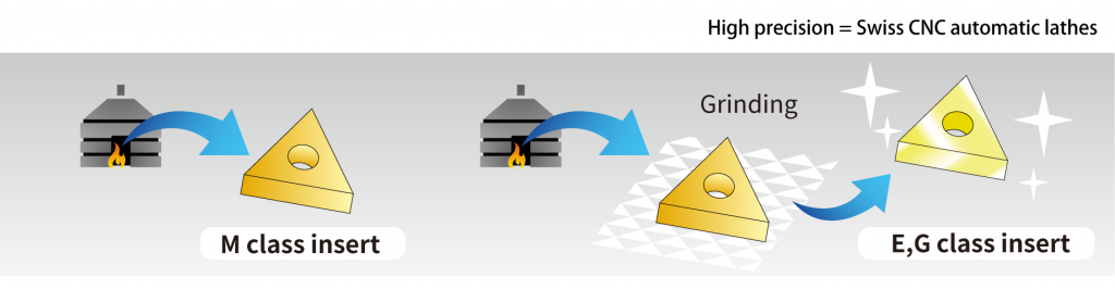 Difference 4. Coatings types: PVD vs. CVDCoating is an important factor in determining the performance of tools and the quality of workpieces. There are two main types of coatings - CVD and PVD. Which coating is suitable for Swiss CNC automatic lathes? 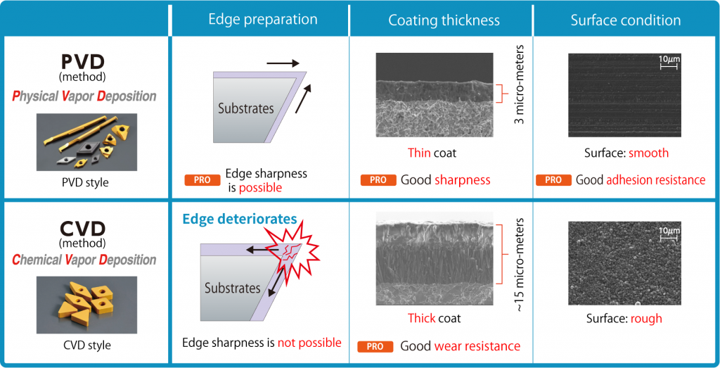 Inserts like “CNMG” and “DNMG” used on CNC lathes are generally CVD coated. CVD coatings can be thick films compared to PVD coatings and have excellent abrasion resistance. But, because it is a thick film coating, it is easy to cause deterioration and there is a disadvantage of a rough coating surface. Swiss-type CNC automatic lathe machining requires high precision, sharpness is important, so PVD coatings are more suitable due to thin film coatings achieving sharp edges. As shown in the figure above, PVD coatings have excellent sharpness, dimensional stability, and welding resistance making it the ideal coating style for Siwss-type CNC automatic lathes. Do you still have questions about the difference between tooling used for a Swiss type CNC lathe and traditional CNC lathe?
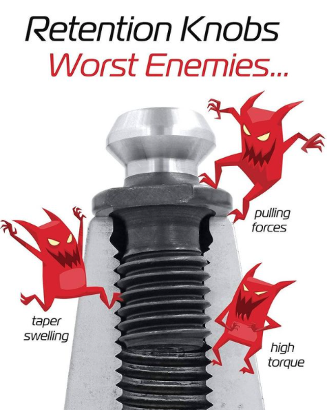
NTK offers a large lineup of tools specialized for CNC automatic lathes. If you are having issues machining, please consider contacting us for technical advise. by Bernard Martin Retention Knobs are the critical connection between your machine tool and the tool holder and they are the only thing holding a steep taper tool holder in the machine’s spindle. Techniks has recently introduced their MegaFORCE retention knobs that have some rather unique features when compared to standard pull studs. Before delving into the features of the MegaFORCE pull studs, let's review some things that you may not know, or think about, on a daily basis.
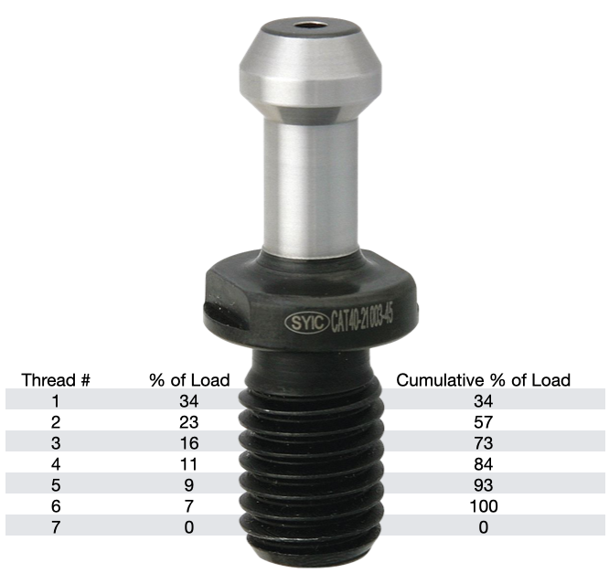
According to Haas, you should expect a service life of about 6000-8000 hours for a retention knob. Most all rotary toolholder manufacturers state that you should be replacing your pull studs at least every three years. However, if you're running multiple shifts, 24-7, making lots of tool changes, making very heavy cuts with long reach or heavy cutting tools, and/or have ball lock style grippers instead of collet type grippers used on the retention knob, you will probably need to replace your studs at least every six months. Given the spindle speeds that we are running at to remain competitive, retention knobs are not an item that you want to take a chance on breaking. I can tell you firsthand that 5 pound toolholder with a drill in it flying out of the spindle at 23,000 RPM is not something you want to experience. METAL FATIGUE: WHY THEY FAILPull studs encounter catastrophic failure as a result of metal fatigue. The metal fatigue can be caused by a number of reasons including poor choice of base material, engineering design, machining process, poor heat treatment, and, sometimes, they have just met or exceeded their service life. We're going to dig into each of these reasons below but first let's look at some threading fundamentals.
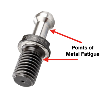
The load on each subsequent thread decreases from there, as show in the table. Any threads beyond the first six are purely cosmetic and provide no mechanical advantage. Additional threads beyond the sixth thread will not further distribute the load and will not make the connection any stronger. That is why the length of engagement of the thread on a pull stud is generally limited to approximately one to one & a half nominal diameter. After that, there is no appreciable increase in strength. Once the applied load has exceeded the first thread's capacity, it will fail and subsequently cause the remaining threads to fail in succession. RETENTION KNOB DESIGNRepetitive cycles of loading and unloading subject the retention knob to stress that can cause fatigue and cracking at weak areas of the pull stud. What are the weak areas of a standard retention knob?
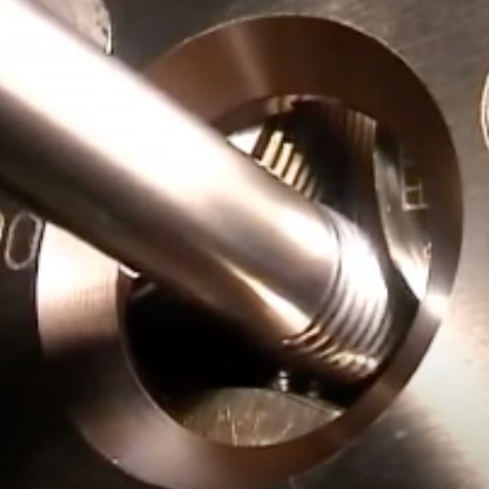
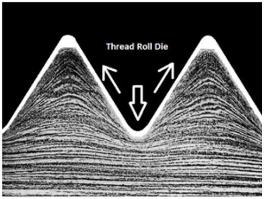
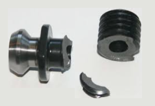
The most common failure point for a retention knob is at the top of the first thread and the underside of the pull stud where the grippers or ball bearings of the drawbar engage and draw the toolholder into the spindle. Remember, bigger Radii are stronger than sharp corners. More on that soon. 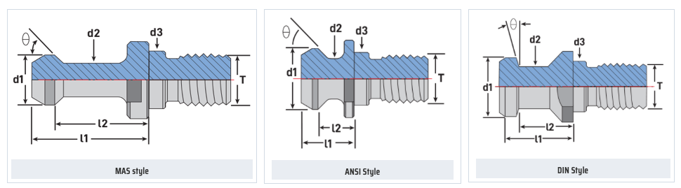 Styles of MegaFORCE Retention Knobs MATERIALNot all retention knobs are made from the same material, however, material alone does not make for a superior retention knob. Careful attention to design and manufacturing methods must be followed to avoid introducing potential areas of failure. Techniks MegaFORCE retention knobs are made from 8620H. AISI 8620 is a hardenable chromium, molybdenum, nickel low alloy steel often used for carburizing to develop a case-hardened part. This case-hardening will result in good wear characteristics. 8620 has high hardenability, no tempering brittleness, good weldability, little tendency to form a cold crack, good maintainability, and cold strain plasticity. There are some companies making retention knobs from 9310. The main difference is the lower carbon content in the 9310. 9310 has a tad more Chromium, while 8620 has a tad more nickel. Ultimate Tensile Strength (UTS) is the force at which a material will break. The UTS of 8620H is 650 Mpa (megapascals: a measure of force). The UTS of 9310H is 820 Mpa. So, 9310H does have a UTS that is 26% greater than 8620H. That said, Techniks chose 8620 as their material of choice because of the higher nickel content. Nickel tends to work harden more readily and age harden over time which brings the core hardness higher as the pull stud gets older. The work hardening property of 8620 makes it ideally suited for cold forming of threads on the MegaFORCE retention knobs. It should be noted that some companies are using H13. H13 shares 93% of their average alloy composition in common with 9310. ROLLED THREADS VS. CUT THREADS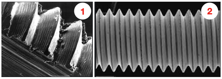 A cut thread, image 1, has a higher coefficient of friction due the the cutting process, while a roll formed thread, image 2, has a lower coefficient of friction which means that it engages deeper into the toolholder bore when subjected to the same torque. You will notice that Cutting threads tears at the material and creates small fractures that become points of weakness that can lead to failure. Rolled threads have burnished roots and crests that are smooth and absent of the fractures common in cut threads. Rolled threads produce a radiused root and crest of the thread and exhibit between a 40% and 300% increase in tensile strength over a cut thread. The Techniks MegaFORCE retention knobs feature rolled threads that improve the strength of the knob by 40%.
Also, unlike thread cutting, the grain structure of the material is displaced not removed.
By comparison, cut threads interrupt the grain flow creating weak points. MEGAFORCE GEOMETRIC DESIGN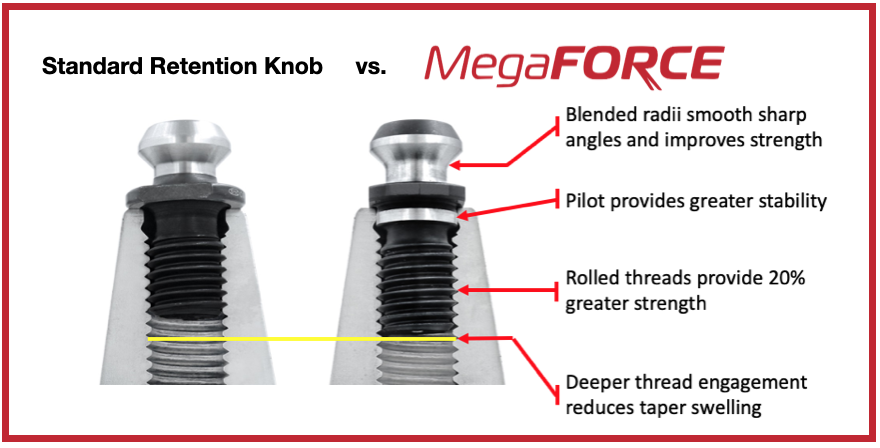 Overall Length There are some claims that a longer projection engages threads deeper in the tool holder preventing taper swelling. While a deeper thread engagement can help prevent taper swelling, applying proper torque to the retention knob is an effective way to reduce taper swelling. An over-tightened retention knob may still cause taper swelling regardless of how deep it engages the threads of the tool holder. Additionally, the longer undercut section above the threads presents a weak point in the retention knob.
Ground Pilot There is a ground pilot, underneath the flange, which provides greater stability. The pilot means the center line of the tool holder and pull stud are perfectly aligned. Magnetic Particle Tested Each Techniks MegaFORCE retention knob is magnetic particle tested to ensure material integrity and physical soundness. MegaFORCE retention knobs are tested at 2.5X the pulling forces of the drawbar.
RETENTION KNOB BEST PRACTICESIn order to maximize the life of your retention knob and prevent catastrophic failure here are some technical tips to keep your shop productive and safe.
Special thanks for Greg Webb at Techniks and Mike Roden from Fette Tools/ Turning Concepts, for providing technical insights.
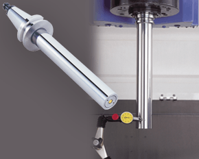
A machine’s spindle is one of the key links in the machining chain. In other words, if there are irregularities inside or at the face, they can show up on your part. It makes regular inspection and spindle maintenance critical to getting the most out of your equipment and maintain process efficiency. These three accessories, the Dyna Contact Taper Gage, the Dyna Test Bar and the Dyna Force Measurement Tool, can help you perform this maintenance easily without eating into valuable spindle time. Dyna Contact Taper Gage
Dyna Test Bar
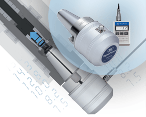
With the help of a dial indicator, you can uncover any runout while safely spinning the spindle at a very low RPM and verify the parallelism of Z-axis motion. Dyna Force Measurement Tool
The Dyna Force measurement tool provides a precise digital reading that reveals reduction in retention force in increments of 0.1kN. If you would like a demonstration for any of these tools contact us or set up an appointment for one of our Next Generation Tooling engineers to visit you!
We are very excited to announce that we are now able to offer on-site technical training to YOUR machinists at YOUR location! This is offered at no charge to customers who use any of the manufacturer's whom we represent in California and Nevada. However, just because you don't purchase things from us, don't feel left out! We also offer on-site topic specter training on any of the following topics for $150/hour. Each presentation lasts about 2 hours. The presentations last approximately 45-60 minutes with the remaining time for Q&A and discussion about unique applications in your facility.  Training Classes Available: Machining 101
Advanced Part Manufacturing:
|
Technical Support BlogAt Next Generation Tool we often run into many of the same technical questions from different customers. This section should answer many of your most common questions.
We set up this special blog for the most commonly asked questions and machinist data tables for your easy reference. If you've got a question that's not answered here, then just send us a quick note via email or reach one of us on our CONTACTS page here on the website. AuthorshipOur technical section is written by several different people. Sometimes, it's from our team here at Next Generation Tooling & at other times it's by one of the innovative manufacturer's we represent in California and Nevada. Archives
March 2024
Categories
All
|

 RSS Feed

About
|
© 2024 Next Generation Tooling, LLC.
All Rights Reserved Created by Rapid Production Marketing
|
