|
Technical Blog excerpt courtesy of Techniks USA Collets come in many different types and sizes. Here is an overview of three of the more popular types of collets, along with the pros and cons of each system. ER Collets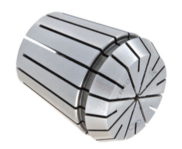 ER collets have between a 0.020” and 0.040” holding range The ER collet system has become very popular due to the flexibility of the system to hold a variety of cutting tool shank types including drills, end mills, and taps. Also, ER collets provide several solutions for increasingly popular coolant-through cutting tools. Most standard ER collets have between a 0.020” and 0.040” holding range, making them a good choice when needing to hold odd-sized cutting tool shanks. This holding range also means fewer ER collets are required to hold a range of cutting tool shank diameters as opposed to other collet systems like TG. The popularity of the ER collet system has led to several variations to hold a wide assortment of cutting tool shanks. Some ER collets have been modified with squares at the bottom to hold taps. Others have been modified to provide quick-change capabilities or compensation, also called “float”, for rigid tapping cycles as shown in the images below. Specialized ER ColletsOther modifications include special slotting designs that seal around the cutting tool shank and force coolant through channels in coolant-through tooling, as well as modifications to include coolant ports in the collet that direct coolant to the cutting area. TG Collets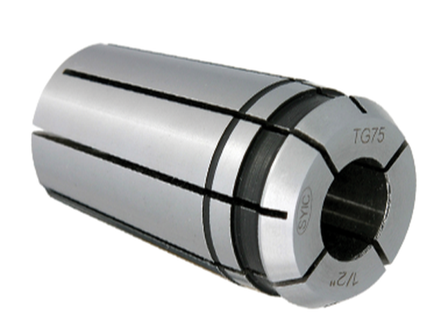 TG collets have about the same accuracy as DA collets, but because there are more slots, and therefore more faces clamping on the cutting tool shank, they tend to deliver greater holding power. TG can be a good solution for larger shank diameter cutting tools, but they generally limit how far down into a pocket you can reach due to interference with the collet nut, as TG collet nuts tend to be quite large. TG collets are not as popular as ER collets for several reasons. Most notably, the larger diameter collet nuts can require the use of extended end mills to avoid interference from the collet nut when milling pockets. Also, since TG collets have a very small collapse range, they are intended for use with one size cutting tool shank. ER collets, by contrast, offer a large collapse range that can be helpful when clamping odd-shank diameter tools. On the flip side, TG collets tend to have a bit more holding power than ER collets due to the collet base having a 4° taper as opposed to the 8° taper found in ER collets. This can make TG collets a good choice when machining with longer-length cutting tools. Double-Angle (DA) Collets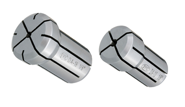 Please stop using DA collets in CNC Machining Double-Angle (DA) collets have been around for a long time and continue to be used in the market. There are, however, many issues associated with DA collets of which users should be aware.
Let's just clear the air and say it: Don't use them. If you have them in your shop, replace them with ER Collets and ER Collet Chucks as soon as possible and you will recoup the cost of the new holders and collets in your tool life probably within a month or two. One of the primary issues with DA collets is that they essentially clamp on the cutting tool shank with only two opposing faces in the I.D. bore. DA collets have four slots in the front of the collet and four slots in the back of the collet creating four clamping faces. However, when DA collets are tightened towards the lower end of their collapse range, two of the faces tend to be pushed out of the way so only two of the faces are clamping on the cutting tool shank. This may cause some runout at the nose when the tool is inspected in a presetter. Additionally, when the tool begins cutting and side forces are applied to the cutting tool, the cutting tool tends to deflect into the area where the faces are not clamping on the tool shank. This results in excessive chatter that dramatically reduces tool life and results in rough surface finishes. You will be hard-pressed to find a quality end mill holder manufacturer endorsing the performance of their tooling in DA collets.
0 Comments
About the author: Jack Burley, Vice President of Sales and Engineering and Big Kaiser Precision Tooling Inc. Micromachining, cutting where the volume of chips produced with each tool path is very small, is not a high-speed operation in relation to chip load per tooth. Rather, it involves a high spindle speed relative to cutter diameter. The part may be physically larger, but details of the part require ultra-small profiles achieved only by micromachining. In other words, micromachining is not limited in scope to only miniature parts. 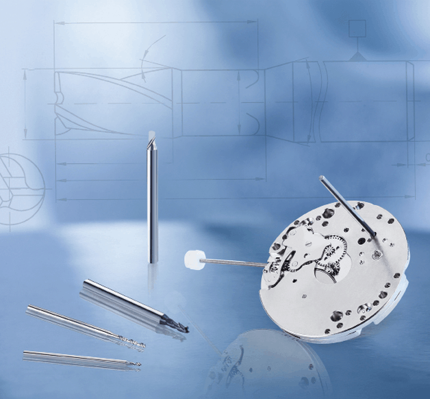 Big Kaiser considers tools with <3mm to be micro tools with unique geometric considerations. TOOLHOLDING In medical work, where tight tolerances are standard, dynamic runout; the measurement of the spindle at high speeds, performed using laser or capacitance resistance technology, and balance must be controlled to deliver and maintain viable tool life.
A holder with 0.00060" runout accuracy produced nearly two-thirds fewer holes, only 800. In this scenario, the shop could save hundreds of dollars a month in carbide costs – as well as labor costs due to less tool changing – by making one smart tool holder choice. Holder attributes that can boost production include symmetrical design, a perfectly concentric collapse of the collet around the cutter, and a ball-bearing raceway nut with precision-ground threads. CHALLENGES While these characteristics are good rules of thumb, things change fast in this field and, like our customers, we must adapt as trends emerge. Batch sizes are getting smaller. Bone screws, for example, were typically run on multi-axis, Swiss-type lathes where the same tools and programs ran for days at a time. Traditionally, prototyping in this arrangement was not an option because of the complexity and time involved in programming and setup. Today’s need for customized sizes demands flexibility and quick changeover to remain productive. We are investing a large portion of our research and development (R&D) in tackling this challenge. We are working on hydro-clamping tool holder systems that could make the decades-long approach of using ER collets obsolete. It would make it possible, for example, to perform a simple drill change on a gang slide in seconds. COOLANTS Another trend in medical manufacturing being driven by the U.S. Food and Drug Administration (FDA) is clean machining without the use of water-soluble coolants.
We are focusing on two features:
 Matching medical components to each patient demands flexibility. This hydro- clamping tool holder system for Swiss-type lathes would make the decades-long approach of using ER collets obsolete by making it possible to perform a simple drill change on a gang slide in seconds. TOOLING Tool considerations also must be taken into account to keep up with the demanding medical field. Better results often cannot be achieved by simply increasing spindle speeds or using smaller tools; a deeper understanding of cutters is necessary. We consider tools with diameters <3mm to be micro tools. These aren’t simply smaller versions of their macro counterparts. They have geometric considerations all their own. For example, the 1mm Sphinx drill can run at 80xD. But this is only possible because the cylindrical shaping extends further down the tool, closer to the tip, to facilitate pecking and maintain strength. Tool carbide should be ultra-fine grain (nano or submicron grain size) to ensure high abrasion resistance and good toughness. Coatings are valuable too, but it’s important to understand how coatings can negatively impact micro tool performance. Micro tools have extremely fine surface finishes and sharp cutting edges. Coatings can fill in valuable space – a flute on a drill, for example – needed for proper chip evacuation, which is critical in these applications. Coatings must be ultra-thin (<1µm) and smooth; our experience shows that misapplied coatings result in poor tool life due to breakage; the coating reduces cutting edge sharpness, increasing torque force on the drill. When coating is necessary, consult with the cutting tool manufacturer to provide this directly. Chips and small tooling naturally do not get along well. Compensating for low spindle speeds with tools that have more flutes support an ideal feed rate, but chip evacuation may suffer. Determining the appropriate chip load – as close to the cutting edge as possible – allows operations at the highest possible spindle speed, accelerating the cycle and improving surface finish. Optimal conditions exist when the chip load is relatively equal to the cutting edge radius. Many micro end mills are designed so the cutting edge radius has a positive rake angle to create a shearing action. A chip load less than the cutting edge radius often results in a negative rake angle where the tool rubs rather than cuts. This increases the force required and generates more heat which can result in built-up edges and poor tool life. A chip load significantly bigger than the cutting edge radius often leads to premature failure because the tool is not robust enough to withstand such forces. MACHINE TOOLS
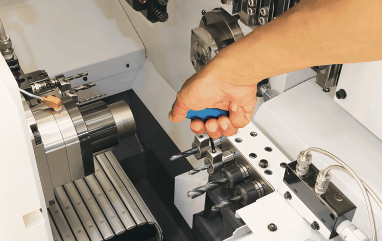
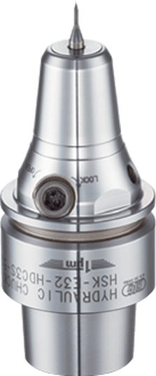
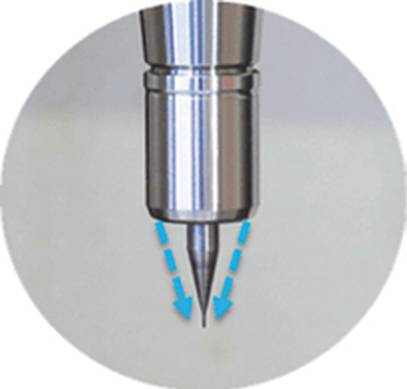
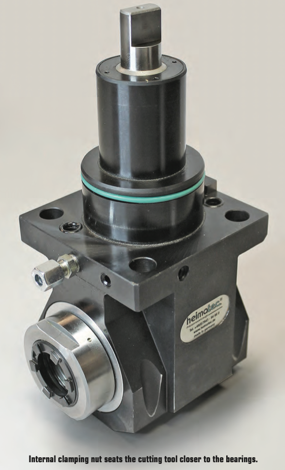
Micromachining requires machine tools with very high sensitivity, fine resolution in the feed axis, and very precise spindles capable of high speed with low dynamic runout. For micro-drilling operations, specialized micro machines are best. Micro milling machines are suited for small tools and small workpieces. They are characterized by spindle speeds faster than 50,000rpm using small HSK tool holders such as HSK-E32, E25, or E20. With the right holder, tool runout can be controlled to less than 1µm (0.000040") at the cutting edge, ensuring sub-micron accuracy. In medical micromachining, understanding each piece of the equipment puzzle is critical. It’s also important not to make assumptions based on other tools or parts you may have worked with, especially in more standard sizes. Invest the right time and energy in gearing up for the next medical job and you’ll get more parts done right faster. A REVIEW OF THIS MACHINING METHOD, THE BASIC CONCEPTS AND SOME EXCITING DEVELOPMENTS IN THE TECHNOLOGY by Preben Hansen, President, Platinum Tooling Technologies Inc. 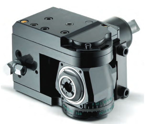 Universal style adjustable tool might be the ideal solution for families of parts. Live tooling, as a component on a lathe, is specifically manipulated by the CNC to perform various milling, drilling and other operations while the workpiece is being held in position by the main or sub spindle. These components, whether BMT or VDI, are also called driven tools, as opposed to static tools, that are used during turning operations. All live and static tools are built per the machine tool builder’s specification for each of the various models they produce. A key to running a successful job shop or production department is to partner with a supplier who can meet the tooling needs for all or most of the machines on your floor. 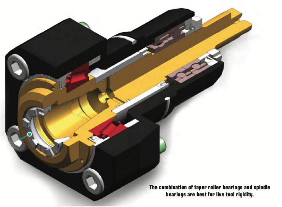 Most often, live tooling is offered in standard straight and 90º angle head configurations with a wide range of tool output clamping systems, including ER collet chuck, arbor, Weldon, Capto, whistle notch, hydraulic, HSK, CAT, ABS and a variety of custom or proprietary systems developed by the many suppliers to the industry. When the need arises for a new machine tool, careful consideration should be made to determine which live tools are appropriate for your application. While a standard machine tool package will help you get started, it is important to anticipate job and volume changes, as well any unforeseen machining challenges from the beginning, in order to avoid machine downtime. This short article is meant to give you a set of parameters to consider when evaluating the live and static tooling to use in your shop or production department. Simply stated, you need to do as much evaluation of your process, when determining the proper tooling to be used, as you did when you evaluated the various machines available for purchase. This fact is often overlooked and that can be a critical error, in the long run. Your examination can range from the simple (external vs. internal coolant, for example) to the sublime (adjustable or multi-spindle configurations) to the custom tool, that may be required and built to suit your special application. Finding a supplier who has an in-house machine shop for the preparation of special tools is a great value-add. Tool life is the product of cutting intensity, materials processed, machine stability and, of course, piece parts produced. Two seemingly identical job shops can have vastly different tooling needs because one is automotive and one is medical, or one specializes in the one-off and low-volume work, while the other has a greater occurrence of longer running jobs. The totality of your operation determines the best tooling for the machines being purchased. Bearing construction and the resulting spindle concentricity drive the life of any tool. You might find that just a 10-15% greater investment in a better design can yield both longer lasting cutters and consistently superior finish on your products. Of course, the stability and rigidity of the machine tool are always critical factors. Bevel and spur gears that are hardened, ground and lapped in sets are best for smooth transition and maximum torque output. Taper roller bearings are consistently superior to spindle bearings in live tool milling applications, so look for a combination system to get the highest rigidity possible. Also, look for an internal vs. external collet nut, so the cutting tool seats more deeply in the tool, as superior performance will result. 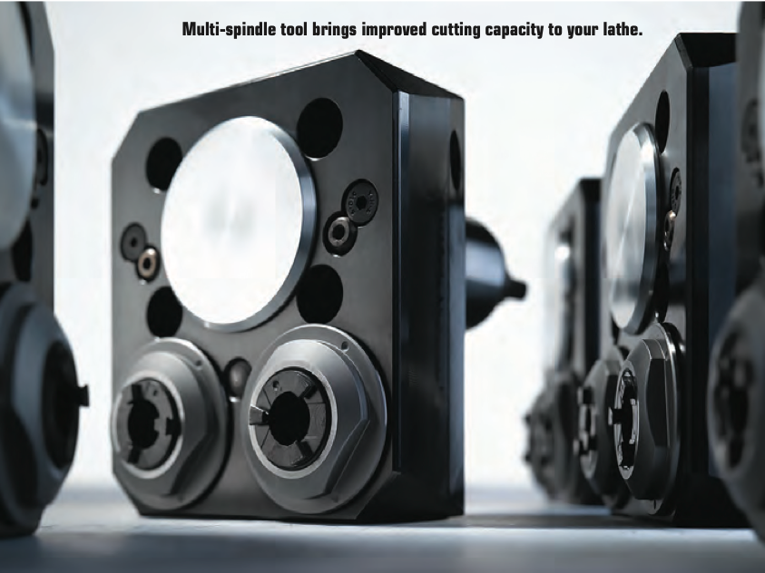 Likewise, high pressure internal coolant might be desirable. Look for 2000 psi capabilities in 90º tools and 1000 psi in straight tools.You need to ask another question, namely, is the turret RPM sufficient to handle the work to be done? It’s possible that a live tool with a built-in speed increaser, often called a speed multiplier, would be helpful. Would it be beneficial to move secondary operations to your lathe? Gear hobbing can be accomplished in this manner, as can producing squares or flats, through the use of polygon machining. Standard live tooling most often is best suited to production work, where the finish, tolerances and cutter life are critical, while quick-change systems may be better suited to the shop producing families of products and other applications where the tool presetting offline is a key factor in keeping the shop at maximum productivity. It’s a given in our industry that when the machine isn’t running, the money isn’t coming.
Dedicated tools for large families of products may often be desirable for some applications, but do consider whether a flexible changing system would be more appropriate. Talk to your tooling supplier for the various options, before making that determination. If standard ER tooling is suitable for the work, there are many good suppliers. It is important though, to pay close attention to the construction aspects noted above. For a quick-change or changeable adapter system, there are fewer suppliers in the market, so seek them out and be sure they can supply the product styles you need for all your lathe brands. 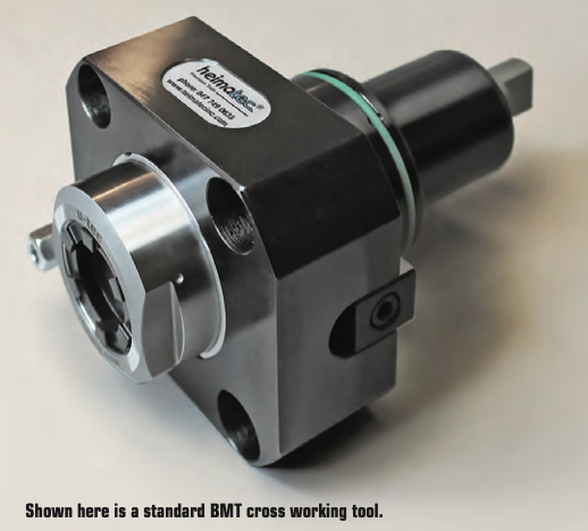 Now, an application example showing clear evidence of the value of testing live tool performance... One company was performing a cross-milling application using an ER 32 output tool on a Eurotech lathe, running 10 ipm at 4000 rpm. They were making three passes with a cycle time of 262 seconds and were having difficulties with chatter on the finish, while producing 20,000 pieces per year. The annual cost of the machining was over $130,000. By using an alternative live tool with an ER 32AX output, internal collet nut design, with the same parameters, they were able to produce the part in a single pass with a smooth finish and cycle time of just 172 seconds. Over the course of the year, this yielded a cost savings of $45,000, approximately 20x the cost of the tool. The bottom line is the bottom line, as the accountants tell us. In the end, you may not need a universal adjustable tool or a multi-spindle live holder or even a quick-change adapter system but do consider all these options. Talk to your machine builder and several tool suppliers, plus the most important people in this equation, your shop personnel, as their input is invaluable to keeping you up and running in a profitable, customer-satisfying scenario. The author welcomes questions, comments and additional input from readers. Please contact Preben Hansen at 847-749-0633 or phansen@platinumtooling.com. Mr. Hansen has over 30 years in tooling and is considered a leading authority on the topic in the North American machine tool market.
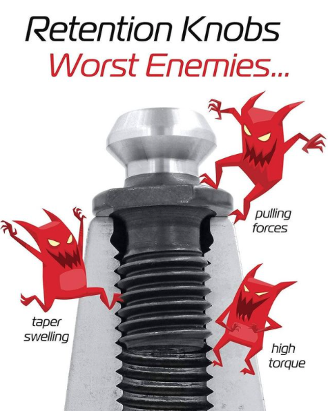
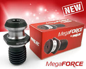
by Bernard Martin Retention Knobs are the critical connection between your machine tool and the tool holder and they are the only thing holding a steep taper tool holder in the machine’s spindle. Techniks has recently introduced their MegaFORCE retention knobs that have some rather unique features when compared to standard pull studs. Before delving into the features of the MegaFORCE pull studs, let's review some things that you may not know, or think about, on a daily basis.
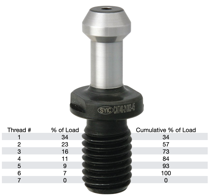
According to Haas, you should expect a service life of about 6000-8000 hours for a retention knob. Most all rotary toolholder manufacturers state that you should be replacing your pull studs at least every three years. However, if you're running multiple shifts, 24-7, making lots of tool changes, making very heavy cuts with long reach or heavy cutting tools, and/or have ball lock style grippers instead of collet type grippers used on the retention knob, you will probably need to replace your studs at least every six months. Given the spindle speeds that we are running at to remain competitive, retention knobs are not an item that you want to take a chance on breaking. I can tell you firsthand that 5 pound toolholder with a drill in it flying out of the spindle at 23,000 RPM is not something you want to experience. METAL FATIGUE: WHY THEY FAILPull studs encounter catastrophic failure as a result of metal fatigue. The metal fatigue can be caused by a number of reasons including poor choice of base material, engineering design, machining process, poor heat treatment, and, sometimes, they have just met or exceeded their service life. We're going to dig into each of these reasons below but first let's look at some threading fundamentals.
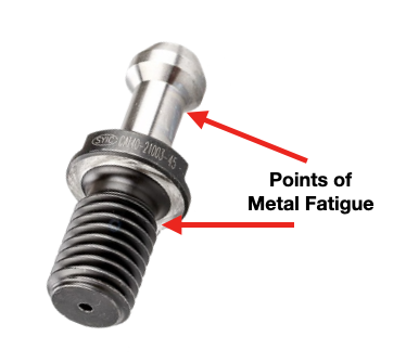
The load on each subsequent thread decreases from there, as show in the table. Any threads beyond the first six are purely cosmetic and provide no mechanical advantage. Additional threads beyond the sixth thread will not further distribute the load and will not make the connection any stronger. That is why the length of engagement of the thread on a pull stud is generally limited to approximately one to one & a half nominal diameter. After that, there is no appreciable increase in strength. Once the applied load has exceeded the first thread's capacity, it will fail and subsequently cause the remaining threads to fail in succession. RETENTION KNOB DESIGNRepetitive cycles of loading and unloading subject the retention knob to stress that can cause fatigue and cracking at weak areas of the pull stud. What are the weak areas of a standard retention knob?
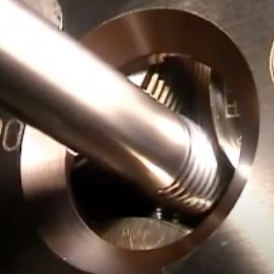
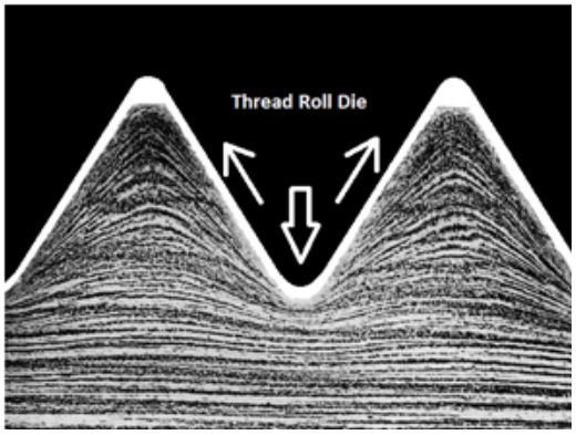
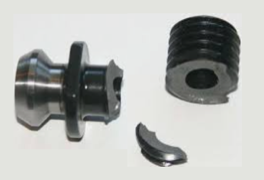
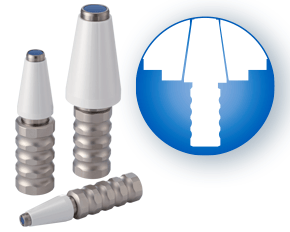
The most common failure point for a retention knob is at the top of the first thread and the underside of the pull stud where the grippers or ball bearings of the drawbar engage and draw the toolholder into the spindle. Remember, bigger Radii are stronger than sharp corners. More on that soon. 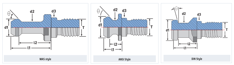 Styles of MegaFORCE Retention Knobs MATERIALNot all retention knobs are made from the same material, however, material alone does not make for a superior retention knob. Careful attention to design and manufacturing methods must be followed to avoid introducing potential areas of failure. Techniks MegaFORCE retention knobs are made from 8620H. AISI 8620 is a hardenable chromium, molybdenum, nickel low alloy steel often used for carburizing to develop a case-hardened part. This case-hardening will result in good wear characteristics. 8620 has high hardenability, no tempering brittleness, good weldability, little tendency to form a cold crack, good maintainability, and cold strain plasticity. There are some companies making retention knobs from 9310. The main difference is the lower carbon content in the 9310. 9310 has a tad more Chromium, while 8620 has a tad more nickel. Ultimate Tensile Strength (UTS) is the force at which a material will break. The UTS of 8620H is 650 Mpa (megapascals: a measure of force). The UTS of 9310H is 820 Mpa. So, 9310H does have a UTS that is 26% greater than 8620H. That said, Techniks chose 8620 as their material of choice because of the higher nickel content. Nickel tends to work harden more readily and age harden over time which brings the core hardness higher as the pull stud gets older. The work hardening property of 8620 makes it ideally suited for cold forming of threads on the MegaFORCE retention knobs. It should be noted that some companies are using H13. H13 shares 93% of their average alloy composition in common with 9310. ROLLED THREADS VS. CUT THREADS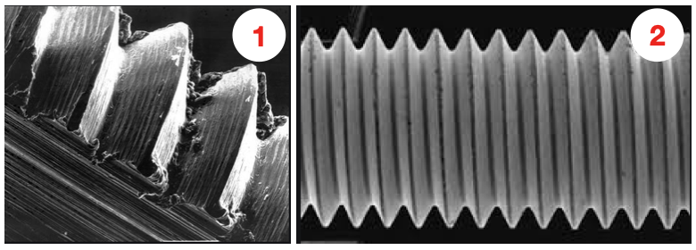 A cut thread, image 1, has a higher coefficient of friction due the the cutting process, while a roll formed thread, image 2, has a lower coefficient of friction which means that it engages deeper into the toolholder bore when subjected to the same torque. You will notice that Cutting threads tears at the material and creates small fractures that become points of weakness that can lead to failure. Rolled threads have burnished roots and crests that are smooth and absent of the fractures common in cut threads. Rolled threads produce a radiused root and crest of the thread and exhibit between a 40% and 300% increase in tensile strength over a cut thread. The Techniks MegaFORCE retention knobs feature rolled threads that improve the strength of the knob by 40%.
Also, unlike thread cutting, the grain structure of the material is displaced not removed.
By comparison, cut threads interrupt the grain flow creating weak points. MEGAFORCE GEOMETRIC DESIGN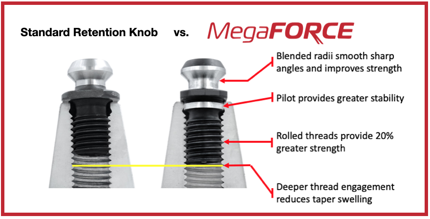 Overall Length There are some claims that a longer projection engages threads deeper in the tool holder preventing taper swelling. While a deeper thread engagement can help prevent taper swelling, applying proper torque to the retention knob is an effective way to reduce taper swelling. An over-tightened retention knob may still cause taper swelling regardless of how deep it engages the threads of the tool holder. Additionally, the longer undercut section above the threads presents a weak point in the retention knob.
Ground Pilot There is a ground pilot, underneath the flange, which provides greater stability. The pilot means the center line of the tool holder and pull stud are perfectly aligned. Magnetic Particle Tested Each Techniks MegaFORCE retention knob is magnetic particle tested to ensure material integrity and physical soundness. MegaFORCE retention knobs are tested at 2.5X the pulling forces of the drawbar.
RETENTION KNOB BEST PRACTICESIn order to maximize the life of your retention knob and prevent catastrophic failure here are some technical tips to keep your shop productive and safe.
Special thanks for Greg Webb at Techniks and Mike Roden from Fette Tools/ Turning Concepts, for providing technical insights.
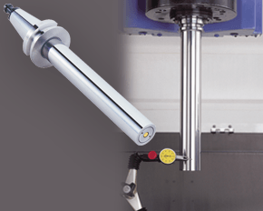
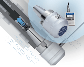
A machine’s spindle is one of the key links in the machining chain. In other words, if there are irregularities inside or at the face, they can show up on your part. It makes regular inspection and spindle maintenance critical to getting the most out of your equipment and maintain process efficiency. These three accessories, the Dyna Contact Taper Gage, the Dyna Test Bar and the Dyna Force Measurement Tool, can help you perform this maintenance easily without eating into valuable spindle time. Dyna Contact Taper Gage
Dyna Test Bar
With the help of a dial indicator, you can uncover any runout while safely spinning the spindle at a very low RPM and verify the parallelism of Z-axis motion. Dyna Force Measurement Tool
The Dyna Force measurement tool provides a precise digital reading that reveals reduction in retention force in increments of 0.1kN. If you would like a demonstration for any of these tools contact us or set up an appointment for one of our Next Generation Tooling engineers to visit you!
A guest blog from BIG KAISER. 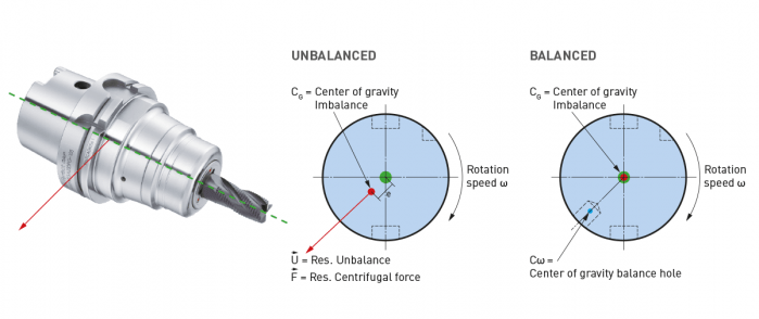 High-speed machining started getting popular in the ‘90s, especially in aerospace where they replaced fabricating processes with machining monolithic parts like wing struts from billets. Machine tools capable of spinning cutting tools at tens of thousands of RPM made it easier to produce these parts quickly. Like machines, holders adapted. The centrifugal forces they had to manage in order to keep tools cutting correctly became extreme. The toolholding systems available at that time were found not to be as effective as the shallower 1-to-10 taper ratio of the German hollow taper shank, hohl shaft kegel (HSK) in German. The HSK has since been standardized to ISO specifications (12164-1, -2). HSK is now available in several sizes and forms to fit with small to large machines. For the most part, the market has settled on the form A for general milling. It has been adopted in Japan, North America and Europe and is truly one of the only worldwide-side toolholder standards. Form E or F is for high-speed machining. The forms have different features depending on the standard they follow. In the end, to achieve efficient tool life, proper finish and productivity in high-speed work, holders need to be as rigid, compact and short as possible to keep the whole assembly stable. What to know when choosing a high-speed tool holder
When it comes to balancing holders, the quality G2.5 is widely used in the industry and is described in the ISO 1940-1 (issued in 2003) standard. However, this quality class is often over-specified and is in many cases not economically or technically feasible, especially when applied to smaller and lighter tools. Standards often applied to tools are more suited for rigid rotors and are practical in a broader use for balancing.
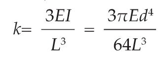
However, it cannot be applied to a complete system of spindles, tool holders and tools adequately and within technical constraints. For example, a tool to be compliant will have to be balanced to less than 1 gmm/kg at a speed of 25,000 rpm, which in turn corresponds to a mass eccentricity of less than 1 μm. This allowable tolerance is less than the interchange accuracy for even HSK, essentially negating all the costs and time for balancing the tool to such a strict tolerance. For this reason, all BIG KAISER tool holders are balanced according ISO 16084 (issued in 2017) specifically developed for rotating tool systems. ISO 16084 focuses on the interaction between spindle and tool factoring in the allowable load on the spindle bearings generated by the tool’s imbalance. This load must not exceed one percent of the dynamic load capacity of the spindle bearings. According to ISO 16084, the allowable unbalance tolerance is specified in [gmm] and is not expressed using a special quality grade [G]. In conclusion, BIG KAISER does not indicate any G-values for balancing quality, but rather the maximum rotational speeds of the individual tool holder. The BIG Kiaser MEGA holder program includes a variety of styles that can be used up to 40,000 RPM. They guarantee 100 percent concentricity and runout accuracy down to .00004" at the nose. They are built specifically to withstand speed and forces required in today’s high-throughput environment. For more information on BIG KAISER's approach to balancing tool holders, click here. To learn more about our high-performance tool holders here.  Spindles and tool holders are in a constant battle with the forces of nature, with this battle becoming more and more difficult with heavier cuts and longer projections. Chattering and deflection have always been the bane of machinists’ existence, so much so that the sight of a long and slender toolholder will immediately cause goosebumps. If you understand why a long tool holder behaves the way it does, you’ll know that there are ways to fight back against this bending. Every machinist knows that short and stubby holders are more resistant to deflection than long and slender holders. You’ve also probably heard that, if possible, you’ll want most of your cutting forces to be axial rather than radial. Not only does this fight chatter in operations like boring, but your spindle also is better equipped to handle loads in this axis. However, these options aren’t always going to be on the table, especially in unavoidable long-reach situations and many milling operations. In this constant battle with tool deflection, much time and effort has been spent designing shorter holders, stiffer tools, and clever anti-vibration geometry and materials. But oftentimes, the body diameter(s) of the holder can be overlooked as a means of increasing rigidity, especially in situations where it is all you have to work with. This is a serious shame, as you’ll soon discover. The concept of dual-contact technology has been around for years, existing in many different forms but always with the same goal of capitalizing on this untapped potential of rigidity. For those who don’t know, dual contact refers to the shank contacting the spindle taper and the spindle face simultaneously. Oftentimes, the solution involved ex post facto alterations to the spindle or tool holder, such as using ground spacers or shims to close the gap, for example. In other words, there was no standard solution, and if you wanted dual contact, you would have to be prepared to spend time and money either buying modified tool holders or modifying them yourself to adapt them to your spindle. BIG-PLUS emerged as a solution to this issue. Essentially, both the spindle and tool holder were ground to precise specifications so that they closed the gap between spindle face and flange in unison (while depending on very small elastic deformation in the spindle). What this meant is that operators were able to confidently switch BIG-PLUS tooling in and out of a BIG-PLUS spindle and achieve guaranteed dual contact. Not only that, but standard tooling could still be used in a BIG-PLUS spindle if necessary, and vice versa. Though not technically an international standard, it’s been adopted by many machine tool builders because of the clear performance improvements and simplicity. In fact, BIG-PLUS spindles come standard on more machines than you would think. We often come across operators that have machines with BIG-PLUS spindles and don’t even realize it. 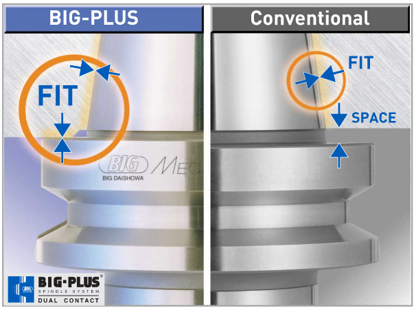 How exactly does dual contact help with tool rigidity? The torque (or moment) exerted by the cutting forces is maximized at the point where the holder and spindle meet, the base of the tool holder. With standard CAT40 tool holders, this would be the gage line diameter. When the holder contacts the spindle face via BIG-PLUS, the effective diameter would be the larger diameter of the v-flange, since this is the new anchoring point of the holder and spindle. So, you are beefing up the diameter at the point where the reactionary force is greatest. It’s not too much of a leap to conclude that a larger effective diameter will give you more rigidity. That being said, you may still be asking yourself: does such a seemingly small increase in diameter really make a difference? To understand the effect of BIG-PLUS, you must understand the physics behind it. Imagine a simple scenario in which a tool holder is represented by a cylindrical bar that is fixed at one end and free-floating at the other. In other words, a cantilever beam. If you think about it, this is essentially what a tool holder becomes once it’s secure in the spindle. Now, let’s introduce a radial force F that acts downward at the suspended end of the bar, which represents a cutting force you would encounter when milling or boring, for example. The bar, as you might expect, will want to bend downward. It’s similar to how a diving board bends when someone stands at the end, though less exaggerated. 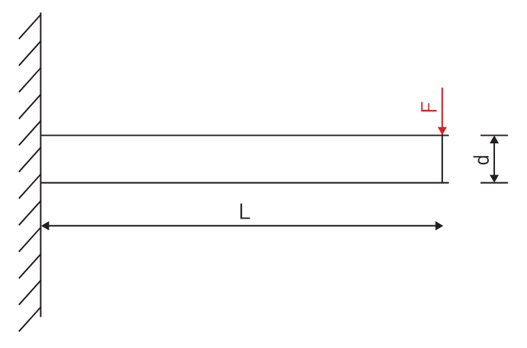 It’s possible to predict the amount of deflection (or inversely, bending stiffness) at the end of this hypothetical bar if you know its length, diameter and material. The expression below represents the stiffness k at the end of the bar where d=diameter, L=Length and E=Modulus of Elasticity
I won’t ask you to do any math here, I just want you to look at the equation. We can see that increasing d will increase the value of k, while increasing L will decrease the value of k, since it’s in the denominator of the equation. This certainly makes sense if you think about it: a short and squat bar (large d, small L) will be more rigid than a long and slender bar (small d, large L). Something interesting to note is that d is raised to the 4th power, while L is only raised to the 3rd power. Diameter affects rigidity an entire order of magnitude more than the length does. This is where the power of BIG-PLUS comes from and is why a small increase in diameter can have such a powerful effect on performance. 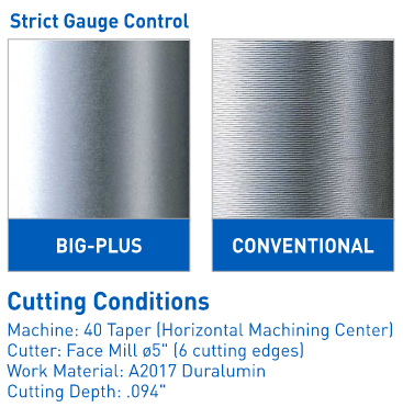 For a CAT40 tool holder, the gage line diameter is Ø44.45 mm and the flange diameter is Ø63.5 mm. Let’s imagine two bars of identical length and material, so L and E remain unchanged. One bar has a diameter of Ø44.45 mm (standard CAT40) and the other has Ø63.5 mm (BIG-PLUS CAT40). If you were to plug these values into the above equation for comparison, you would find that the BIG-PLUS holder results in a k value that is around 4 times greater than the standard bar. Based on this comparison, you could say that a BIG-PLUS holder is 4 times as rigid as an identical standard CAT40 holder, because it is 4 times as resistant to deflection. Think of the tool life and surface finish improvements you would see with a tool that is 4 times more rigid, not to mention the reduction in fretting and potential for reduced cycle time. You would get similar results if you were to make the same comparison for CAT50, BT40, BT30, etc. 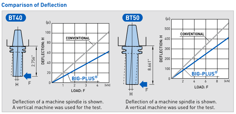 If you’re still not convinced, we can also compare the rigidity in this way: Let’s say there is a Ø63.5 mm BIG-PLUS CAT40 bar of some arbitrary length. One of our more common gage lengths is 105 mm, or just over 4 inches, so let’s use it as an example. You’re probably wondering, at what length would a comparable standard CAT40 holder have an equal stiffness? If we take our stiffness expression and set it equal to itself (one side representing BIG-PLUS, the other non BIG-PLUS), we can plug in this BIG-PLUS holder length and our known diameters to find our unknown non-BIG PLUS length: 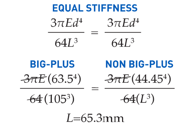 What does this mean? A BIG-PLUS holder of around 4 inches or 105 mm in length will have equal rigidity to a standard CAT40 holder of around 2.5 inches or 65 mm in length. Any experienced machinist will know quite well the difference in rigidity between a 4-inch long holder and a 2.5-inch long holder.
If this is true, we can say that implementing BIG-PLUS is equivalent to a 40% reduction in length in terms of rigidity. Theoretically, a BIG-PLUS tool holder will behave like a standard tool holder that is nearly half of its length! Obviously, we’ve used simple and idealized cases here to represent the complicated and dynamic world of metal cutting. Tool holders, of course, don’t have uniform body diameters or materials and the cutting forces usually aren’t acting in one direction in a constant and predictable way. If our holder necks up and down to different body diameters along its length, which is realistically what happens, each of these sections would be its own microcosm of “beam” that would influence the overall behavior (at that point, finite element analysis on a computer becomes the only practical way to predict behavior). So, will the advantage of BIG-PLUS really be as dramatic as our hand-calculated classical beam theory suggests? Probably not, but it depends on the tool holder/tool. Most cases will follow our simple model quite closely in practice; others not so much. If nothing else, we’ve demonstrated how dramatically the flange contact of BIG-PLUS can influence rigidity, at least in a purely mathematical sense. As if you needed any more reasons to be on the BIG-PLUS bandwagon besides increased rigidity, you will also eliminate Z-axis movement at high speeds, improve ATC repeatability and decrease fretting. This means that you will take heavier cuts, scrap less parts, and increase tool and spindle life. BIG-PLUS isn’t a new idea by any means, but with a proven track record of tackling tough jobs, it’s hard to imagine working in a modern machine shop and not taking advantage of what it has to offer. If you’re still not convinced, we can also compare the rigidity in this way: Let’s say there is a Ø63.5 mm BIG-PLUS CAT40 bar of some arbitrary length. One of our more common gage lengths is 105 mm, or just over 4 inches, so let’s use it as an example. You’re probably wondering, at what length would a comparable standard CAT40 holder have an equal stiffness? If we take our stiffness expression and set it equal to itself (one side representing BIG-PLUS, the other non BIG-PLUS), we can plug in this BIG-PLUS holder length and our known diameters to find our unknown non-BIG PLUS length: 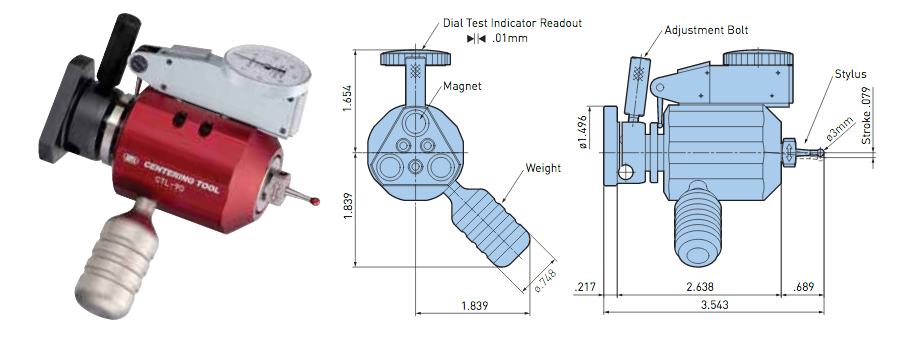 With this innovative centering tool from Big Kaiser, spindles and tools can be centered quickly and easily. It's ideal for limited spaces within small lathes. The Centering Tool is a static dial gauge for easy centering.
|
Technical Support BlogAt Next Generation Tool we often run into many of the same technical questions from different customers. This section should answer many of your most common questions.
We set up this special blog for the most commonly asked questions and machinist data tables for your easy reference. If you've got a question that's not answered here, then just send us a quick note via email or reach one of us on our CONTACTS page here on the website. AuthorshipOur technical section is written by several different people. Sometimes, it's from our team here at Next Generation Tooling & at other times it's by one of the innovative manufacturer's we represent in California and Nevada. Archives
July 2024
Categories
All
|
 RSS Feed

About
|
© 2024 Next Generation Tooling, LLC.
All Rights Reserved Created by Rapid Production Marketing
|
