Tough, Precise, and Fast —Carmex HBA carbide grade is available today for tomorrow’s materials10/21/2020  As more applications require the use of super-hard alloys, manufacturers are demanding tooling that can deliver precision threads and high production in less time. To meet these challenges, Carmex Precision Tools Ltd. has engineered carbide grade HBA — an extra-fine, submicron grade with high toughness for optimized performance on hardened steel Titanium and super alloys including Hastelloy, Inconel and Nickel base alloys up to 62 HRc. Available for internal and external threading in both 60° and 55° partial profile, as well as ISO metric and UN, HBA delivers high wear and heat resistance and excellent edge stability. The unique combination of carbide substrate, coating type and edge conditions provide superior performance over extended tool life. Case Study in Threading D2 at 53-56HRc 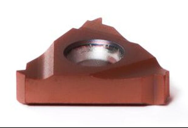 16mm (3/8" I.C.) LAYDOWN INSERT FOR ISO (METRIC) EXT-RH THREAD; PITCH: 01.50mm; GRADE: HBA In a recent test involving an external right-hand thread:
Hard machining is increasingly becoming the rule rather than the exception in complex part production. Carmex HBA was engineered to meet the challenges inherent in threading hard materials while delivering high production and longer tool life. Bring us your most challenging hard threading applications and lets try the new Carmex HBA engineered performance carbide .
0 Comments
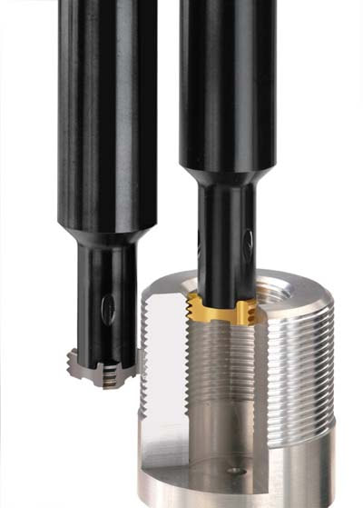
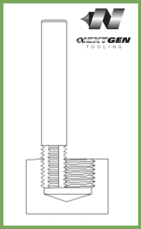
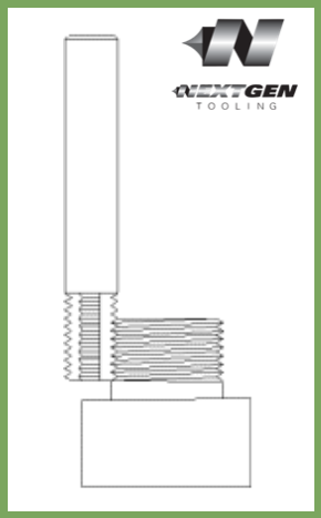
The DMT/DMTH tool family consists of high-performance tools that can be used in the production of internal threads. The circular motion performed by these tools during operation produces the thread hole, the actual thread, and an (optional) chamfer in a single work process. This eliminates the need to switch between tools, saving valuable time.
DMT - THREAD MILLS WITH INTERNAL COOLANT BORE
Features:
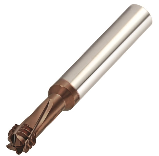
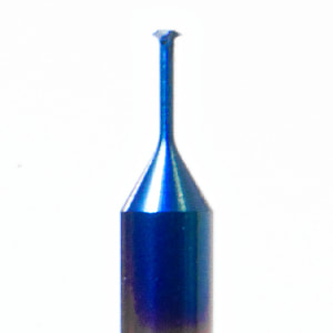
Made from Carmex MT7 Carbide Grade:Sub-micron grade with multi-layer TiAIN coating. This is a general purpose grade, which can be used with all materials. (ISO K10-K20) TECH TIP: For left-hand jobs, use the M04 code in your G-Code programs. DMT - THREAD MILLS WITHOUT INTERNAL COOLANT BORE
Features:
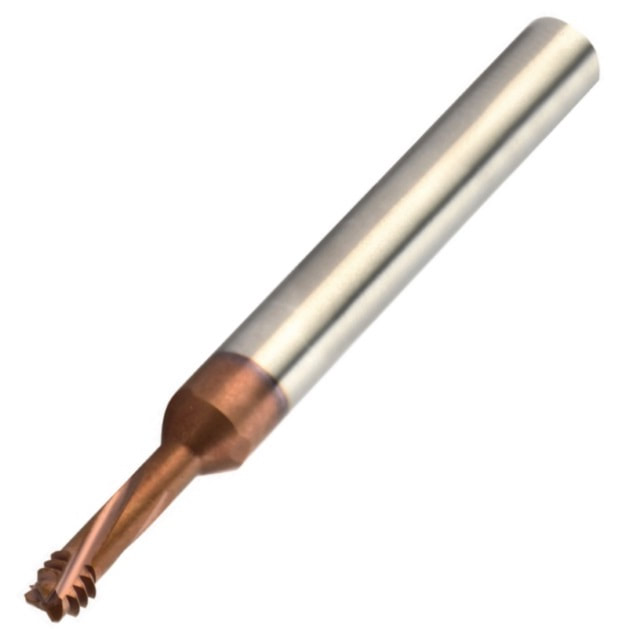
Made from Carmex MT7 Carbide Grade:Sub-micron grade with multi-layer TiAIN coating. This is a general purpose grade, which can be used with all materials. (ISO K10-K20) TECH TIP: For left-hand jobs, use the M04 code in your G-Code programs. DMTH – 3 IN 1 FOR HARD MATERIALS
Features:
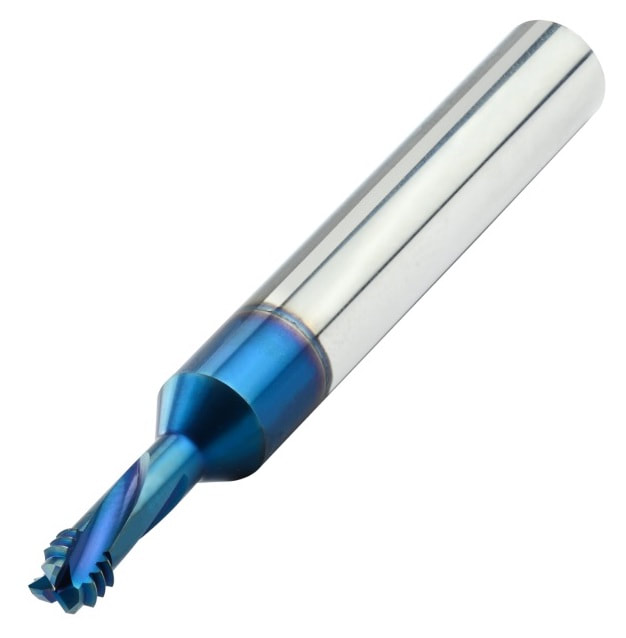
Made from Carmex MT11 Carbide Grade:Ultra-fine sub-micron grade with triple blue PVD coating. TECH TIP: For left-hand jobs, use the M04 code in your G-Code programs. 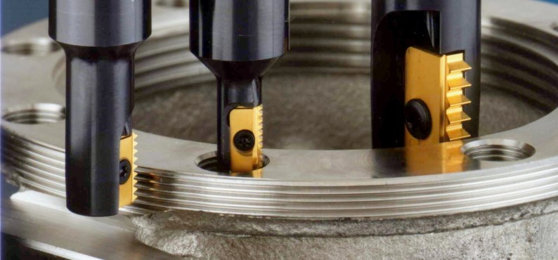 The first step toward understanding thread milling is knowing its advantages and exploring where it could fit in your operation. Although many operators would have no trouble visualizing the use of thread milling on larger size parts, advances in the technology have made it an extremely advantageous choice for even the smallest holes. Most of our customers discovered thread milling — and Carmex — when they consulted their industrial distributors about problems they were having with taps. As parts have become more complex and materials harder to machine, the disadvantages of tapping has become more apparent. By virtue of their design, taps are prone to breakage. The extraction of a broken tap can cause real problems in high-value parts that demand precision thread finishes — not to mention the lost man-hours involved. A frequent cause of breakage involves chip overload, and chip removal has continually been a problem in tapping. For this reason, the use of taps on NC equipment has always presented challenges due to breakage and thread quality. A further disadvantage is the inability of a tap to thread to the bottom of a blind hole. This requires an extra allowance for clearance that is both undesirable and unnecessary. Shorter tool life is another problem and, in automated situations, requires redundant tooling that takes up space in the tool magazine. Thread milling, on the other hand, avoids the difficulties associated with tapping since it not only delivers better chip control but can proceed unimpeded to the bottom of the blind hole. Because of thread interpolation and the use of solid carbide and indexable tooling, breakage is eliminated, vibration is reduced, and a more precise thread and better finish are generated. This in turn translates to greater economy through longer tool life and increased dependability, especially on CNC machines or automated equipment. Versatility is likewise a consideration. Thread milling can be utilized on holes as small as 0.25″ up to the largest sizes. All standard thread profiles are available and, for specialized applications, custom-made tools can be produced, tested and delivered to match tight production schedules. Thread Mill Features
Besides the advantages inherent in thread milling, Carmex offers customers further benefits. Years ago, Carmex engineers perfected the tool design they refer to as their “Helical Advantage™.” By smoothing the engagement of the tool, their products can operate at higher speeds, ensure precision threads, and deliver better overall finish. The Helical Advantage is also a major factor in extending tool life. Before we forget, its also worth mentioning that you should also check out the Carmex Tool Wizard software to speed your start-up. Most important, our Next Gen Tooling team is thoroughly trained and ready to assist you, not only in getting started, but in selecting the right tools for your applications. Whether your operation involves large transfer type equipment, conventional CNC machines, automated lines, or high precision Swiss-style machining, we’ll be happy to work with you to develop the best solutions to your individual needs and advance your processes to the latest in thread milling technology. Over the years, many of our customers have come to us because they were regularly breaking taps.
This meant that the holes had to go from a depth of .150" to .190". The 2-56UN thread’s major diameter was .086", and the drill diameter .070".
Repeatability was nearly impossible on his CNC equipment, and he literally came in every Saturday to tap the holes by hand. When he started talking with us, he was breaking his taps after only 20 holes — an extraordinarily short tool life. By re-examining his technology, and switching to Carmex Precision thread milling, he was able to accomplish the threading of 683 holes with a single thread-mill on his CNC equipment. Despite the number of passes, the wear factor between the first and the last holes could only be measured in tenths, and the customer was able to get the thread detail back to its original .150" full thread depth. Perhaps just as important, his Saturdays are now “tap-free.” We are very excited to announce that we are now able to offer on-site technical training to YOUR machinists at YOUR location! This is offered at no charge to customers who use any of the manufacturer's whom we represent in California and Nevada. However, just because you don't purchase things from us, don't feel left out! We also offer on-site topic specter training on any of the following topics for $150/hour. Each presentation lasts about 2 hours. The presentations last approximately 45-60 minutes with the remaining time for Q&A and discussion about unique applications in your facility.  Training Classes Available: Machining 101
Advanced Part Manufacturing:
Next Generation Tooling is excited to offer some new services coming in 2015! Below is a very fast video of our new training series on Tapping which we can present to your manufacturing team at your site. It's a comprehensive overview of screw thread terminology, thread forms, fundamentals of threads, classes of fit, Tap basics, types of chamfers, the tapping process,tap types, screw thread inserts, helix angles, core diameters, re an hook angles, thread reliefs, pitch tolerances, H limits, Tap substrates, Surface treatment and coatings, tapping speeds, tap drill sizes.
This article originally appeared in decomagazine March 2013 entitled "Real Thread Whirling" Edited September 30, 2020 by Bernard Martin to add new video and additional content. 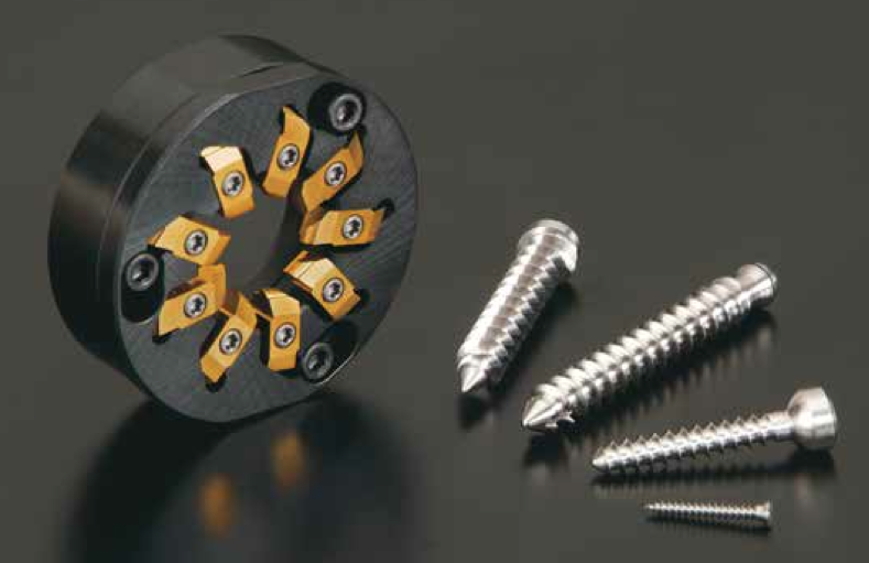 “Thread Whirling” has become a popular process for Swiss machines, especially among bone screw manufacturers. Although most Swiss machine engineers agree that thread whirling delivers outstanding productivity with the highest efficiency vs conventional single point threading, not all engineers know the “Real Thread Whirling” process. NTK first released thread whirling tools with (9) inserts back in 2008. NTK engineers never perceived thread whirling as a complicated process. The complication was not with regards to machining difficulty but in producing the perfect thread form described on the print itself. The so called “Bone Screw” is a major part produced by the thread whirling process. It is quite unique, compared with the other industrial screws, since there are no female threads to mate. Bone screws are attached directly into human or animal bones for medical repair applications. The screw is not expected to be loosened at all once it is fixed in place. The characteristics of bone screws are: larger pitch size and larger screw depth and length as their key function is to be tightened into bones rigidly and as quick as possible. As a result of this uniqueness, inspection of screw forms has become extremely difficult. Due to the larger helix angle to make a high pitch thread form, you cannot visually see the cross section at all with a common optical comparator. What you can check with an optical comparator is only the peripheral or bottom diameter of the thread. 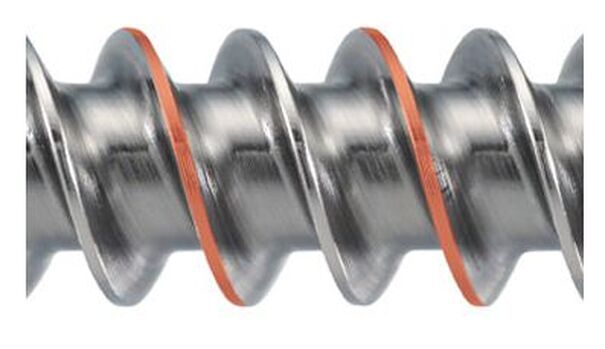 6AL-4V Titanium Bone Screw that has been created via Thread whirling The only way to measure the real thread form of a bone screw is to inspect it with a (CMM) Coordinate Measuring Machine. However, there are not many manufactures which use CMM type of measurement machine for the inspection after machining. Most of them focus on visual inspection of thread form and surface roughness and use an optical comparator for the final inspection. Another surprise for NTK engineers, is the fact that even in manufacturers that have the very latest machines, well experienced and highly educated staffs, the engineers make small adjustment on a helix angle or pitch size when they cannot get the ideal thread form. 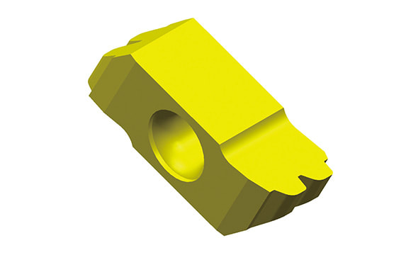 Thread whirling carbide Insert for the 6al4V Titanium Bone Screw pictured As you may understand, if you change the helix angle or pitch size, thread form itself could be totally out of print specifications. Why does this happen? One factor comes from the uniqueness of bone screw: There is no female thread. That is, if the thread form is made close enough to the print, the screw can perform its function to be tightened rigidly to a bone since there is no mating surface (female thread). The other comes from difficulty in designing thread whirling inserts due to complexity of thread form itself. Having a visual image of thread whirling process in your mind is extremely difficult. Thread whirling inserts are set on the round cutter body and the cut- ter is attached to the spindle which is tilted with a helix angle. The spindle revolves at a higher rotation (like 3000 rpm) while the bar stock revolves in the same direction but at a much slower rate like 10-30 rpm. During this rotating process, each thread whirling insert machines the bar stock while they rotate much faster than the bar stock. The spindle and the inserts tilt to make thread form and the inserts shave or cut bar stock not only at the center of the bar stock but also the upper or the lower side of the bar stock. 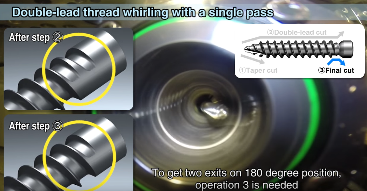 NTK Thread Whirling -Machine a double lead screw in a single pass Conventional, single point threading inserts are designed with exactly the same thread form as the thread itself because it always machines with regards to the center of the bar stock. On the other hand, thread whirling inserts cannot be designed with the same concept because the actual machining point always varies on the upper or lower side of the bar stock. However, there are some competitor’s thread whirling inserts designed with the identical methodology as single point threading. With this incorrectly designed thread whirling inserts, bone screw manufactures are frequently required to re-make the inserts, in some cases, not one time but several times. Or, they are forced to make inappropriate manual adjustment on the helix angle or pitch size to obtain the thread form which looks closer to the prints specification. NTK thread whirling does not require such guesswork process manipulation. Thanks to the design capability of our inserts we can obtain perfect threads right from the start. This process designing technology is now patented. Recently, to reduce surgery hours, bone screws with double lead threads are becoming more popular. This industry trend is creating another challenge for most bone screw manufacturers. Producing double lead bone screws require longer machining times than single lead screws. Most manufacturers machine the 1st lead within the guide bushing length and then machine the same length with the 2nd lead while the guide bushing is still holding on to the bar stock. As a result, they need multiple passes to achieve a double lead thread form bone screw. If the bone screw is very long then this process has to be repeated the full length of the bone screw which is a more time consuming process. As you can imagine, single pass machining of the double lead bone screw is the best solution to improve productivity. To enable single pass machining of double lead screw, both inserts must have a different geometry ground on 1st and 2nd threads. This is simply because thread whirling machining is calculated with regards to the upper and lower point of the screw’s centerline. This process generates the double lead bone screw in a single pass cutting both the 1st and the 2nd leads at the same time.
NTK thread whirling designing technology and highly accurate insert grinding ability can produce the per- fect thread whirling inserts the first time. This feature enables double lead bone screw manufactures to achieve single pass machining. We believe that you will appreciate NTK’s highly advanced thread whirl- ing system technology once you use NTK’s double or triple thread whirling tools. When your machine is equipped with the correct helix angle setting, correct tool setting and a NTK thread whirling system, you will experience “real Thread Whirling” which can produce perfect thread form screws. NTK is looking forward to your inquiries from those who eager to have perfect thread form from the beginnings, of course with no incorrect manual adjustment, or to improve your double, triple lead screws productivity. via OSG Tap & Die Jan 2, 2023 editors note: This article has been updated with new drawings and videos since it's original publication date. 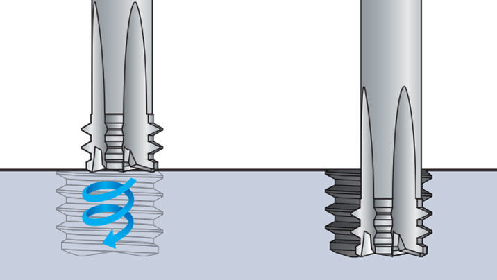 The machining technique for OSG’s thread mills have been developed for thread milling on a 3-Axis, 4-Axis and 5-Axis CNC controlled machine tool. The thread is processed by advancing one pitch feed per revolution in the axial direction, utilizing the planet-like rotation and revolution movements of the tool. Internal and external thread, right or left hand threads can all be produced with this one tool, simply by changing the direction of rotation and/or feed. This process is called Helical Interpolation and will be explained in greater detail below. Threading Process
The transition between the start and the finish of the milling operation must be smooth, and the appropriate amount of feed is essential for minimizing milling resistance. There are many different methods for using this tool, but our research has shown that this technique provides the most precise and efficient operation. 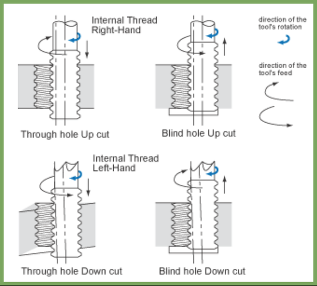 Understanding Thread Mills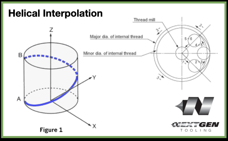 Figure 1. Helical Interpolation Any three axis mill that is capable of helical interpolation can be used for thread milling. Helical interpolation involves three axes moving simultaneously. Two axes, 'X' and 'Y', move in a circular motion while the 'Z' axis moves in a linear motion. For example, the path from point A to point B (Figure 1) on the periphery of the cylinder combines a circular movement in the 'X-Y' plane with linear movement along the 'Z' axis. The 'X' and 'Y' circular motion will determine the diameter of the thread. The 'Z' axis linear motion will cut the pitch (or lead) of the thread.
All of the straight flute thread mills are for internal threads only. All of the staggered tooth thread mills will cut both the internal and external threads. The helical thread mills over 0.187 diameter will also cut both internal and external threads. Staggered tooth thread mills have every other tooth removed in a staggered pattern; as the tool rotates the adjacent flute fills in for the tooth that was removed. This helps to reduce side cutting pressure, thus reducing chatter. This can be extremely beneficial in small external sizes and for set-ups that lack rigidity. Helical fluted thread mills are also designed to reduce side cutting pressure by distributing the cutting pressure along a helical flute. Although these tools cost slightly more, their high performance design allows for less chatter and higher feed rates. How to Use Thread MillsTo produce internal threads, drill the minor thread diameter to its appropriate size. Then, position the thread mill to the required depth. Next, mill either the 'X' or 'Y' axis to the required thread pitch diameter. With small sizes and with difficult to cut material, it may be necessary to remove the material in several passes. It is always best to "arc-in" and "arc-out" when thread milling. Any "arc-in" and "arc-out" movements must have a corresponding 'Z'-axis motion during the 'X-Y' circular moves. For example, if the "arc-in" is over 90 degrees, the 'Z'-axis departure must be 1/4 of the thread pitch. (90 degrees is 1/4 of a circle).
The entire process can be achieved by interpolating in a downward direction and reversing the orbit direction. However, it is highly advisable to do so since the tools will have much less material to remove. If the tool is to be interpolated in an upward direction, spiral interpolation must be used. The same surface feet per minute can be used for thread mills as for end mills of the same size. The feed rate must be slower, however, since thread milling often involves unfavorable length-to-diameter ratios. Also, keep in mind that the thread mills have more surface area contact than an end mill of equal length. Most CNC mills are programmed in inches per minute which is applied at the centerline of the spindle. In internal applications, the outside diameter of the tool will be traveling faster than the centerline of the tool. The reverse is true for external applications. It is best to start out conservatively with feed rates and the number of passes required and adjust upward per good machining practice.
Troubleshooting Threadmillingupdate August 2020: OSG just released this new troubleshooting video that further details some thread milling concepts. |
Technical Support BlogAt Next Generation Tool we often run into many of the same technical questions from different customers. This section should answer many of your most common questions.
We set up this special blog for the most commonly asked questions and machinist data tables for your easy reference. If you've got a question that's not answered here, then just send us a quick note via email or reach one of us on our CONTACTS page here on the website. AuthorshipOur technical section is written by several different people. Sometimes, it's from our team here at Next Generation Tooling & at other times it's by one of the innovative manufacturer's we represent in California and Nevada. Archives
March 2024
Categories
All
|
||||||||||||||||
 RSS Feed

About
|
© 2024 Next Generation Tooling, LLC.
All Rights Reserved Created by Rapid Production Marketing
|
