|
This article originally appeared in decomagazine March 2013 entitled "Real Thread Whirling" Edited September 30, 2020 by Bernard Martin to add new video and additional content. 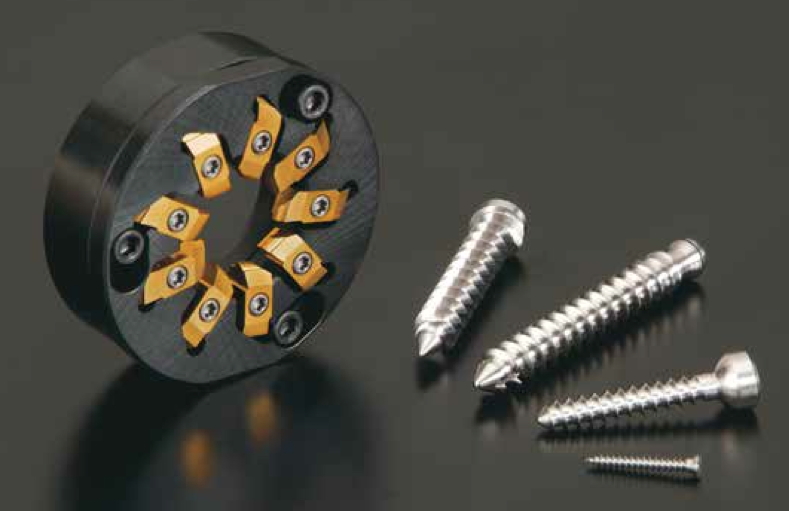 “Thread Whirling” has become a popular process for Swiss machines, especially among bone screw manufacturers. Although most Swiss machine engineers agree that thread whirling delivers outstanding productivity with the highest efficiency vs conventional single point threading, not all engineers know the “Real Thread Whirling” process. NTK first released thread whirling tools with (9) inserts back in 2008. NTK engineers never perceived thread whirling as a complicated process. The complication was not with regards to machining difficulty but in producing the perfect thread form described on the print itself. The so called “Bone Screw” is a major part produced by the thread whirling process. It is quite unique, compared with the other industrial screws, since there are no female threads to mate. Bone screws are attached directly into human or animal bones for medical repair applications. The screw is not expected to be loosened at all once it is fixed in place. The characteristics of bone screws are: larger pitch size and larger screw depth and length as their key function is to be tightened into bones rigidly and as quick as possible. As a result of this uniqueness, inspection of screw forms has become extremely difficult. Due to the larger helix angle to make a high pitch thread form, you cannot visually see the cross section at all with a common optical comparator. What you can check with an optical comparator is only the peripheral or bottom diameter of the thread. 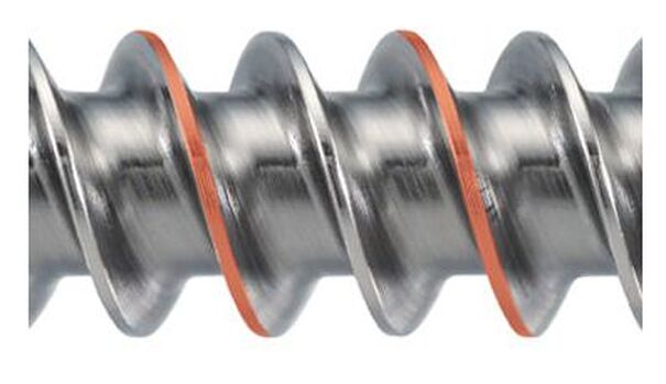 6AL-4V Titanium Bone Screw that has been created via Thread whirling The only way to measure the real thread form of a bone screw is to inspect it with a (CMM) Coordinate Measuring Machine. However, there are not many manufactures which use CMM type of measurement machine for the inspection after machining. Most of them focus on visual inspection of thread form and surface roughness and use an optical comparator for the final inspection. Another surprise for NTK engineers, is the fact that even in manufacturers that have the very latest machines, well experienced and highly educated staffs, the engineers make small adjustment on a helix angle or pitch size when they cannot get the ideal thread form. 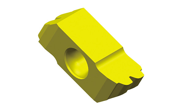 Thread whirling carbide Insert for the 6al4V Titanium Bone Screw pictured As you may understand, if you change the helix angle or pitch size, thread form itself could be totally out of print specifications. Why does this happen? One factor comes from the uniqueness of bone screw: There is no female thread. That is, if the thread form is made close enough to the print, the screw can perform its function to be tightened rigidly to a bone since there is no mating surface (female thread). The other comes from difficulty in designing thread whirling inserts due to complexity of thread form itself. Having a visual image of thread whirling process in your mind is extremely difficult. Thread whirling inserts are set on the round cutter body and the cut- ter is attached to the spindle which is tilted with a helix angle. The spindle revolves at a higher rotation (like 3000 rpm) while the bar stock revolves in the same direction but at a much slower rate like 10-30 rpm. During this rotating process, each thread whirling insert machines the bar stock while they rotate much faster than the bar stock. The spindle and the inserts tilt to make thread form and the inserts shave or cut bar stock not only at the center of the bar stock but also the upper or the lower side of the bar stock. 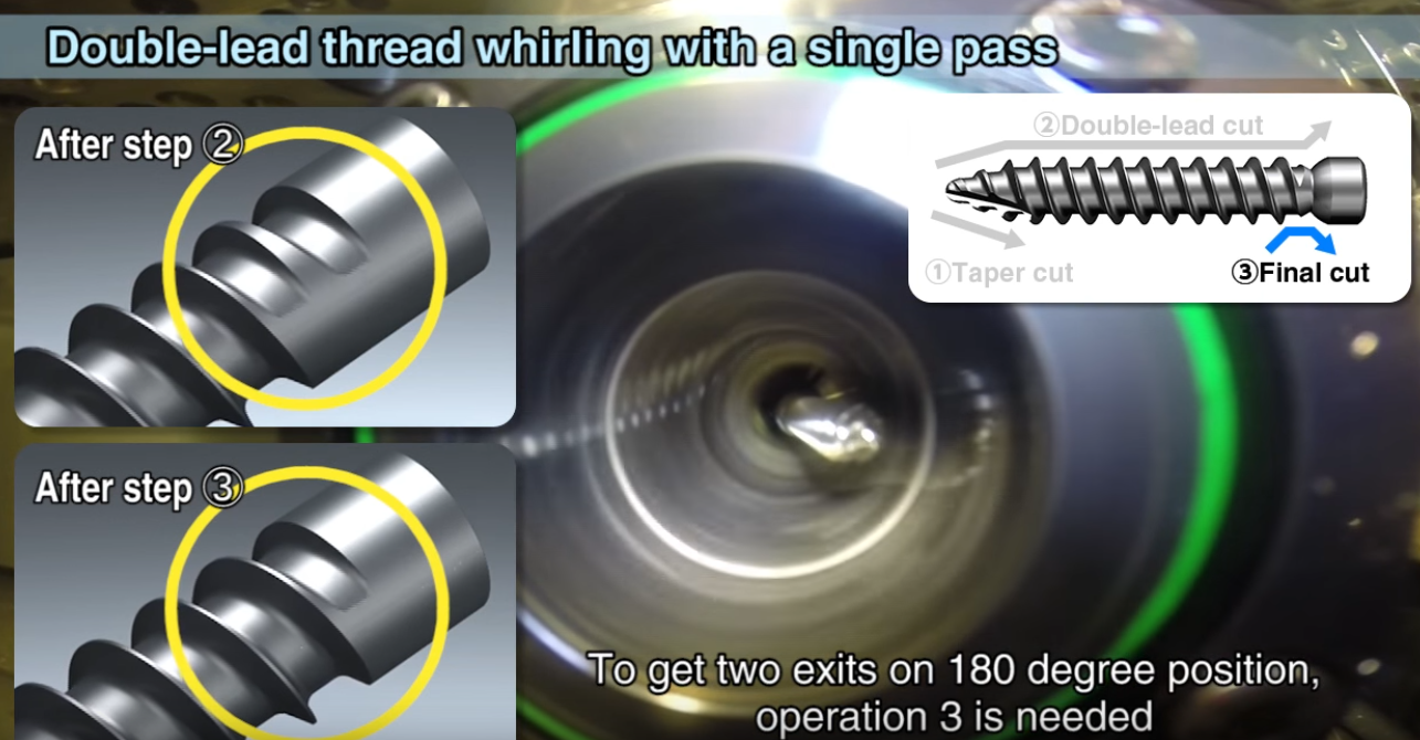 NTK Thread Whirling -Machine a double lead screw in a single pass Conventional, single point threading inserts are designed with exactly the same thread form as the thread itself because it always machines with regards to the center of the bar stock. On the other hand, thread whirling inserts cannot be designed with the same concept because the actual machining point always varies on the upper or lower side of the bar stock. However, there are some competitor’s thread whirling inserts designed with the identical methodology as single point threading. With this incorrectly designed thread whirling inserts, bone screw manufactures are frequently required to re-make the inserts, in some cases, not one time but several times. Or, they are forced to make inappropriate manual adjustment on the helix angle or pitch size to obtain the thread form which looks closer to the prints specification. NTK thread whirling does not require such guesswork process manipulation. Thanks to the design capability of our inserts we can obtain perfect threads right from the start. This process designing technology is now patented. Recently, to reduce surgery hours, bone screws with double lead threads are becoming more popular. This industry trend is creating another challenge for most bone screw manufacturers. Producing double lead bone screws require longer machining times than single lead screws. Most manufacturers machine the 1st lead within the guide bushing length and then machine the same length with the 2nd lead while the guide bushing is still holding on to the bar stock. As a result, they need multiple passes to achieve a double lead thread form bone screw. If the bone screw is very long then this process has to be repeated the full length of the bone screw which is a more time consuming process. As you can imagine, single pass machining of the double lead bone screw is the best solution to improve productivity. To enable single pass machining of double lead screw, both inserts must have a different geometry ground on 1st and 2nd threads. This is simply because thread whirling machining is calculated with regards to the upper and lower point of the screw’s centerline. This process generates the double lead bone screw in a single pass cutting both the 1st and the 2nd leads at the same time.
NTK thread whirling designing technology and highly accurate insert grinding ability can produce the per- fect thread whirling inserts the first time. This feature enables double lead bone screw manufactures to achieve single pass machining. We believe that you will appreciate NTK’s highly advanced thread whirl- ing system technology once you use NTK’s double or triple thread whirling tools. When your machine is equipped with the correct helix angle setting, correct tool setting and a NTK thread whirling system, you will experience “real Thread Whirling” which can produce perfect thread form screws. NTK is looking forward to your inquiries from those who eager to have perfect thread form from the beginnings, of course with no incorrect manual adjustment, or to improve your double, triple lead screws productivity.
1 Comment
Ceramic tools have high resistance to heat and to wear and can be used to machine metals that are extremely hard, and they are chemically stable. These attributes allow them to be used to machine metals at high cutting speeds and in dry machining conditions because it is not necessary to reduce temperatures on the cutting edges of these tools. However, these favorable properties are exchanged in machining for lower toughness when these tools are compared with carbide tools. This deficiency can be offset by selecting an appropriate ceramic cutting grade and the type of tool. Ceramic tools are based primarily on alumina (Al2O3) and silicon nitride (Si3N4) compounds and are available in a variety of grades that include ceramics mixed with other materials and reinforcing whisker materials that make them harder. Oxide ceramics
The materials are molded at pressure more than 4,000 psi and they are sintered at approximately 3,000 degrees F. This process accounts in part for the high density and hardness of these tools. Oxide ceramics are used primarily for rough and finish turning, for grooving of gray and nodular cast iron and for continuous cutting at high cutting speeds without the use of coolant. Ceramic tools are stable at extreme temperatures as high as 4,000 degrees F., unlike carbide and cement tools that contain metallic binders and begin to soften at temperatures greater than 1,000 degrees F. Whiskered ceramicsReinforced or whiskered, ceramics use extremely fine-grained silicon-carbide crystals that are called “whiskers” because they resemble small hairs under a microscope to reinforce and toughen basic ceramic compounds. In ceramic tool materials, single-crystal silicon carbide whiskers, on the order of one micron in diameter and 0.003937 in. (100 microns) in length, are intertwined within the alumina-matrix structure. These whiskers have a tensile strength of about 1 million psi and dramatically improve the fracture toughness of the tool material. They also effectively block and prevent propagation of cracks.  Reinforced ceramics work differently from other cutting materials. With reinforced ceramic cutting tools, the objective in machining is to generate high temperatures ahead of the cutting tool to soften or plasticize the workpiece material. That facilitates the removal of material and a reduction in cutting forces. The ideal cutting temperature in nickel alloy is about 1,800 degrees F, for example. Cutting with ceramic inserts requires high surface speed and balanced feedrates. High speed is necessary to generate the high temperature in the shear zone and to ensure that the heat propagates into the chip-forming zone immediately ahead of the cutter. When cutting speeds are too slow, insufficient heat is generated to soften the material in this zone, and the cutting forces are raised and insert failure occurs. A strategy for using ceramic inserts is to program fewer, but deeper cuts that bury the insert deep in the workpiece. This moves the notch formation further up the face of the insert to an area that has a larger, stronger cross section. Ramping cuts should be programmed to accommodate these tools and fixed depths of cut should be avoided to spread wear over a larger section of the insert. When machining interrupted cuts with reinforced ceramics, it is important to keep the speed of the cutter high. A rule of thumb is to estimate the percentage of voids in the workpiece surface and increase cutting speed by that percentage. This increase in surface speed offsets the loss of heat generation created by the voids. Whiskered ceramics work best on hard ferrous materials and difficult-to-machine nickel-base alloys, including Inconel, Waspoloy and Hastelloy. They do not work well on ferrous alloys below Rc 42 hardness because of the chemical reaction that occurs between iron and the carbon that is part of the silicon carbide reinforcing material. Silicon nitridesCeramics based on silicon nitride offer increased resistance to abrasion and thermal shock and have high fracture toughness. These ceramic tools have a needle-like structure that is embedded in a temperature-resistant grain-boundary. These structures enhance crack deflection, crack bridging and pull-out effects, and lead to superior fracture toughness.  These materials are based on compositions of ceramic powders with high purity. Techniques used to produce these ceramics, including optimized powder processing and gas-sintering, enhance their fracture toughness and high-temperature hardness. Silicon nitrides are well suited for rough machining cast iron, even under unfavorable conditions such as heavily interrupted cuts and varying depths of cut. Silicon nitrides also are used to mill cast iron, even with positive tool geometries. Silicon nitrides are suitable for milling operations that produce chips with large cross sections and require positive tool geometries. When used with powerful machine tools, silicon nitrides enable high cutting speeds (more than 800 in./min.) and feeds (0.2 to 0.3 in./min.) for rough boring cast iron. Silicone nitride tools offer fracture resistance, but their relatively low resistance to chemical wear limits their use in machining nodular cast irons. However, wear-resistant, chemical vapor deposit (CVD) alumina coatings have expanded the range of applications for silicon nitride-based tools to include these difficult-to-machine irons. Gray cast iron and nodular graphite cast iron can be milled at cutting speeds of 500 to 800 in./min or sometimes faster than 1,000 in./min. Five Types of Ceramic Cutting Tools.There are five types os ceramic cutting tools. Here are the basic differences:
ALUMINIUM OXIDE OR WHITE CERAMIC NTK GRADES: HC1, CX3, HW2 Pure alumina strengthened by Zirconium.
MIXED OR BLACK CERAMICS NTK GRADES: HC2, HC4, HC5, ZC4 Alumina with metallic phase of Titanium Carbide and Titanium Nitride which improves thermal conductivity.
SILICON NITRIDE BASED CERAMICS NTK GRADES: SX1, SX2, SX8, SP2
WHISKER REINFORCED CERAMICS NTK GRADES: WA1 Pure alumina structurally strengthens from introduction of Silicon Carbide in the form of whiskers.
SIALONS NTK GRADES: SX5 Alumina substrate strengthened by Silicon Nitride.
The above text is from American Machinist's Cutting Tool Central. For up to the minute information follow them on Twitter @AmericanMachnst |
Technical Support BlogAt Next Generation Tool we often run into many of the same technical questions from different customers. This section should answer many of your most common questions.
We set up this special blog for the most commonly asked questions and machinist data tables for your easy reference. If you've got a question that's not answered here, then just send us a quick note via email or reach one of us on our CONTACTS page here on the website. AuthorshipOur technical section is written by several different people. Sometimes, it's from our team here at Next Generation Tooling & at other times it's by one of the innovative manufacturer's we represent in California and Nevada. Archives
March 2024
Categories
All
|
 RSS Feed

About
|
© 2024 Next Generation Tooling, LLC.
All Rights Reserved Created by Rapid Production Marketing
|
