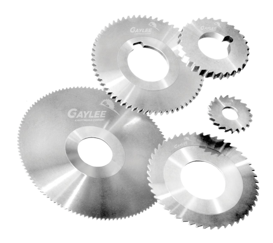
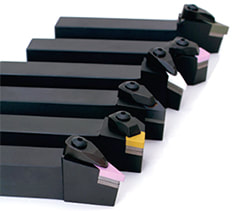
 A human hair is about .0040” thick. Martindale Gaylee solid carbide saws can be manufactured as thin as .0020” which is half the thickness of a human hair. This extreme miniaturization is made possible through their numerous years of experience. At the other end of the spectrum, solid carbide saws can also be made as thick as 1.000” with O.D.’s typically ranging from .250” to 7.500” (6.35mm to 190mm) and tighter than standard tolerances are also available. Keep in mind that all solid carbide saws 2” diameter and larger are manufactured with a standard hub and round key. Martindale Gaylee has a dedicated team of saw-makers unparalleled the world over. From saws to cutting knives to slitters, slotters and cutters...we’re prepared to work with you on your specific application. 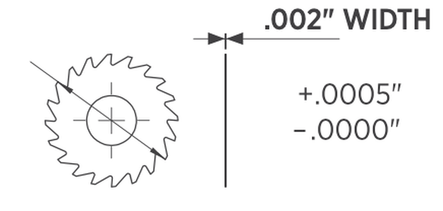 The miniature saw shown on the left above has an O.D. of 3⁄4” with 18 precision teeth. The saw shown on the right has an O.D. of 1⁄2” with 14 precision teeth. Gaylee takes pride in producing precision saws unsurpassed by any other manufacturer for your application.
Get in touch with us with any questions about solid carbide saws!
0 Comments
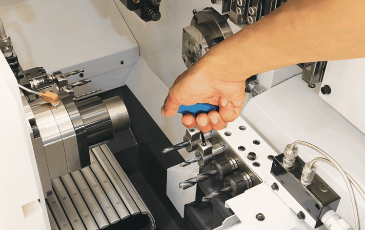
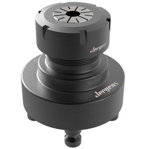
Jergen's 5-Axis ER Collet Fixtures Provide Simple Clamping of Cylindrical Parts in a CNC MIll4/12/2022 Looking for a simple and low profile solution for clamping cylindrical workpieces and round bars? Do you ever need to hold a round shank workpiece and machine it in a CNC Mill?
The ER Collet Fixtures provide a simple and low profile solution for clamping cylindrical workpieces using the same technology you are already familiar with in your rotary toolholders.
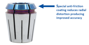
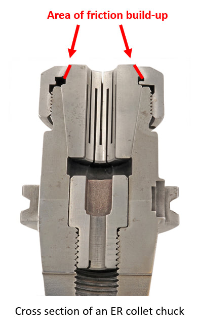
It’s been estimated that a tool with a run-out of 50% of the tool’s chip load will reduce its tool-life by 40%. That means that a 1/8” tool with a 0.00019” chip load per tooth will lose 40% of its tool-life with a run-out of less than 0.0001”. Excessive and inconsistent run-out from a properly setup ER collet chuck assembly typically occurs due to friction build-up between the 30° face of the collet and the collet nut.
 The result?
Other Parlec P3 collet advantages:
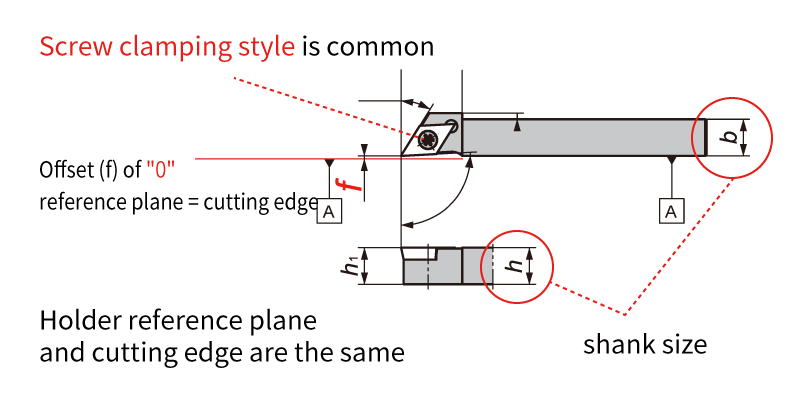
Don’t throw away you ER collet chucks to improve accuracy Try Parlec P3 collets and supercharge your ER collet system.  Put simply, the manufacturing process of boring is enlarging a hole in a piece of metal. There are quite a few different pieces of machinery or approaches that can be used to make holes from lathes and mills to line boring or interpolation. We wanted to do a quick break down of the different kinds of boring tools available to bore holes and/or secondary boring operations. Boring BarsBoring deep holes can involve extreme length-to-diameter ratios, or overhang, when it comes to tooling assemblies. Since it can be difficult to maintain accuracy and stability in these scenarios, we need boring bars to extend tooling assemblies and while maintaining the rigidity to make perfect circles with on-spec finishes. Solid boring bars Typically made of carbide for finishing or heavy metal for roughing, solid boring bars have dense structures that make for a more stable cut as axial force is applied. Damping bars When cutting speeds are compromised, or surface finishes show chatter in a long-reach boring operation, damping bars are an option. They have integrated damping systems. Our version, the Smart Damper, works as both a counter damper and friction damper so that chatter is essentially absorbed.  Boring HeadsBoring heads are specifically designed to enlarge an existing hole. They hold cutters in position so they can rotate and gradually remove material until the hole is at the desired diameter. Rough boring heads Once a bore is started with a drill or by another method, rough boring heads are the choice for removing larger amounts of material. They are built more rigid, to handle the increased depths of cut, torque and axial forces needed to efficiently and consistently make the passes to remove materials. Fine boring heads Fine boring heads are best used for more delicate and precise removal of material that finishes the work the rough boring head started. They are often balanced for high-speed cutting since that’s the best approach for reaching exact specifications. Twin cutter boring heads Most boring heads feature one cutter that cuts as its feed diameter is adjusted by the machine. There are twin cutter boring heads that can speed up cutting and add versatility. For example, the Series 319 and other BIG KAISER twin cutter boring heads include two cutters that can perform balanced or stepped cutting without additional accessories or adjustments by switching the mounting locations of the insert holders that have varied heights. Digital boring heads Traditionally, adjusting boring heads has been painstaking and time-consuming, especially when it’s done in the machine. It’s easy to make mistakes when maneuvering to read the diameter dial and adjusting it to the right diameter. Digital boring heads have a LED that makes precise adjustments much easier.  Starter DrillsSince cutters are on diameter of boring heads and not their face, they are not able to initiate a hole on a flat surface or raw material. Especially in smaller bores, fluted drills called starter drills can be used to get the hole started before rough boring.
Specialty boring heads Back boring and face grooving heads, as well as chamfering insert holders, are available for some of the most common secondary operations, after a hole is bored. We produce specific heads with cutters at the appropriate angles so each of these operations can be done without manually moving the part, changing the tool or adjusting the cutter angle. Modular boring tools Since limiting length-to-diameter ratios is so crucial to boring success, it’s extremely valuable to be able to make your tooling assembly as short as possible. Our modular components are based on a cylindrical connection with radial locking screw that allows for the ideal combination of different kinds of shanks, reductions and extensions, bars, ER collet adapters and coolant inducers. Looking for some help finding the right boring equipment for your next job or new machine? Our engineers are here to help. Get in touch with us here. Written and edited by Bernard Martin PowerCOAT Collet Nuts provide up to a 75% increase in holding power! 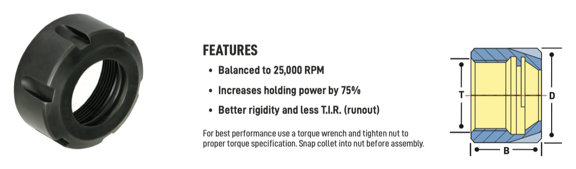 One of the most important elements of the toolholding 'system' is the collet nut. Each toolholder "system" consists of a precision ER tool holder that comes with a special "Power Coated" high power nut that holds tighter than any other nuts. According to Techniks, the 'Power Coat' nut is the secret to their high holding power. Because it holds so tight, the 'Power Coat' nut improves T.I.R., extends carbide tool life, and improves finish in heavy milling operations. Techniks recommends that for best results always tighten the nut to the proper torque using a torque wrench with a tightening stand, and never over-tighten the nut because this can damage both the collet and the collet pocket. To demonstrate the difference between an uncoated and coated collet nut, Mike Eneix, from Techniks did some testing. He took an uncoated, imported nut and put it to the test against the Parlec PowerCOAT nut. Mike took them to the limit to see which one gives you more holding power. Check out the video below! What makes the difference?As anyone knows who has changed a flat tire on their car, tightening down a nut on a 60 degree thread involves some friction as the mating metal surfaces interact. That's why nuts can be a bit 'hot' to the touch when you take them off. The objective with the "Power Coated" nuts was multifold:
First Techniks needed to reduce the coefficient of friction on the thread angle to enable more lubricity for the nut to tighten down farther. As we all know 'heat' causes metal to "grow" so what may at first appear to be tight, in fact, loosens, as soon as you stop tightening it. Second they needed to make sure that the front surface of the collet that engages the shorter 30 degree taper on the front of an ER collet did not 'twist' as the night tightened down. Both problems really involved reducing friction and through a combination of engineering tolerances and unique coating process we believe that we've found the most economical solution to eliminate the use of cheater bars and collet over torque. Here's what they've found out in testing the "Power Coated" Nuts:
“Power Coat” is an innovative, permanent coating that increases clamping pressure of the nut up to 75% compared to standard ER nuts. More holding power reduces the chance of spinning the shank of the tool inside the collet, which can cause premature failure of the collet. A Swiss type CNC automatic lathe and a CNC lathe, they are similar lathe machines, but did you know they are completely different? In this article, the kind folks at NTK Cutting Tools will introduce the 4 differences between the cutting tools used based on the mechanical structure of Swiss CNC automatic lathes and CNC lathes. What is the difference between a “Swiss CNC Automatic Lathe” and a “CNC lathe”?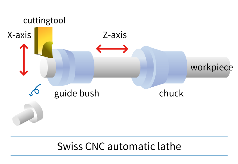
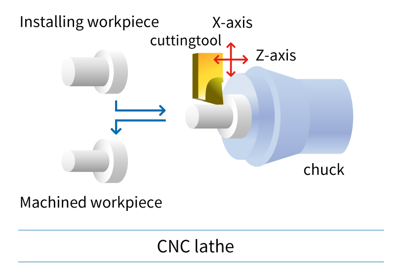
Swiss CNC automatic lathe & CNC lathe: Since the machine structure, workpiece, and size are different, it is important to select the cutting tool accordingly. Now let's take a look at the features of cutting tools used in CNC automatic lathes. Difference 1. HolderThe holder is an important component for achieving chip performance. I will explain the difference between the holder used on a Swiss type CNC automatic lathe and a CNC lathe.
Holders for Swiss CNC Automatic Lathe
CNC Lathe Holders
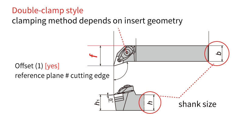
Difference 2. Insert geometry: Positive inserts and Negative insertsCNMG... DNMG...: If you are familiar with machining on CNC lathes, you likely know about insert geometries. The Swiss type CNC automatic lathe is the same type of lathe, but if you are thinking of machining with the same insert, be careful! Inserts such as "CNMG /CNGA..." and "DNMG/DNGA ..." used on CNC lathes have many corners, and the cutting edge is honed or chamfered (edge preparation) and have excellent cutting edge strength. These inserts are ideal for shearing the workpiece material. On the other hand, when a negative insert such as "CNMG/CNGA..." is used on a Swiss type CNC automatic lathe, cutting resistance tends to be high and "chatter" and "work deflection" occur. We recommend using a "positive style" for Swiss CNC automatic lathes. Swiss-type CNC automatic lathes machine workpieces that are smaller in diameter and require higher precision than machining on a CNC lathes. High cutting resistance causes “vibration” and “dimensional defects”, so using a “positive insert” with a relief angle to reduce cutting resistance and achieve stable machining. 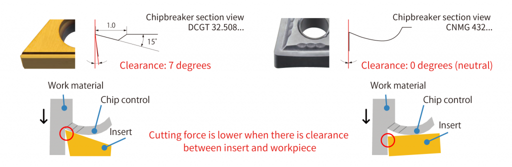 As shown above, the larger the clearance angle (relief), the smaller the area where the tool touches the workpiece. This reduces cutting resistance. b Difference 3. Insert tolerance: G-class and M-class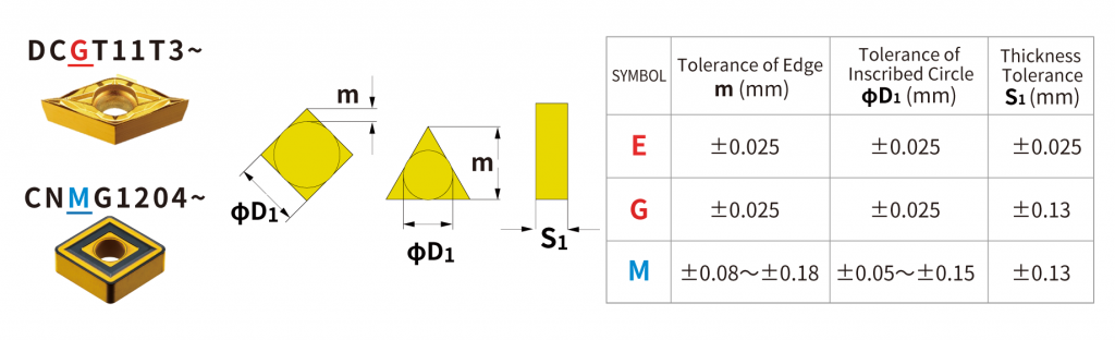 The ISO insert designation includes a tolerance class. I will discuss the difference in insert tolerance classes for Swiss type CNC automatic lathes and CNC lathes. The table above compares the “M” class commonly used on CNC lathes with the “G” class and “E” class commonly used on Swiss SNS automatic lathes. The 3rd letter in the insert part description identifies the tolerance class. Insert such as CNMG… and DNMG… have an M class tolerance. On the other hand, inserts such as DCGT… and CCGT… have a G-class tolerance. As shown in the table, the insert tolerance is very different between the “G” and “M” class. Corner length (m) and insert IC (dia. D1) tolerance affect the accuracy of the cutting edge position, or workpiece dimensions. Thickness tolerance (S1) affects the height of the cutting edge. Swiss-type CNC automatic lathes require high precision machining of small diameter workpieces, so “G-class” or “E-class” with higher tolerance than M-class are used. Also, the upper and lower insert surfaces of G-class and E-class inserts are polished and the outer edges are ground with high accuracy which achieves excellent sharpness. For Swiss CNC automatic lathes, it is strongly recommended to use inserts with “G-grade” and “E-class” tolerances. 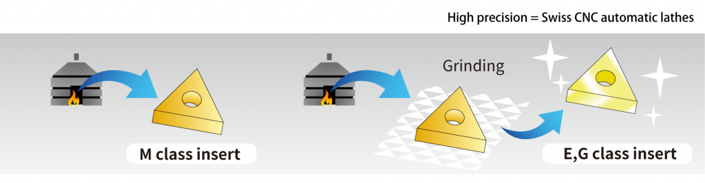 Difference 4. Coatings types: PVD vs. CVDCoating is an important factor in determining the performance of tools and the quality of workpieces. There are two main types of coatings - CVD and PVD. Which coating is suitable for Swiss CNC automatic lathes? 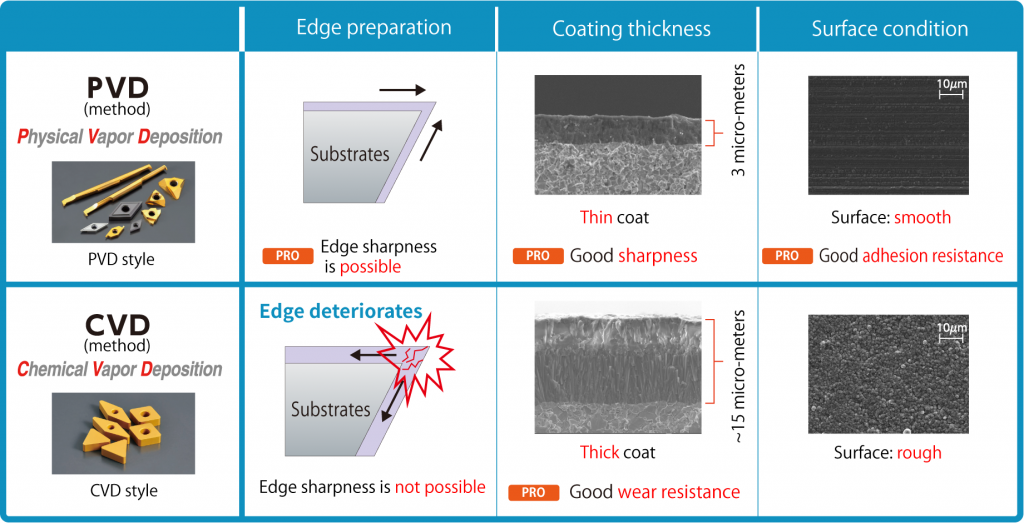 Inserts like “CNMG” and “DNMG” used on CNC lathes are generally CVD coated. CVD coatings can be thick films compared to PVD coatings and have excellent abrasion resistance. But, because it is a thick film coating, it is easy to cause deterioration and there is a disadvantage of a rough coating surface. Swiss-type CNC automatic lathe machining requires high precision, sharpness is important, so PVD coatings are more suitable due to thin film coatings achieving sharp edges. As shown in the figure above, PVD coatings have excellent sharpness, dimensional stability, and welding resistance making it the ideal coating style for Siwss-type CNC automatic lathes. Do you still have questions about the difference between tooling used for a Swiss type CNC lathe and traditional CNC lathe?
NTK offers a large lineup of tools specialized for CNC automatic lathes. If you are having issues machining, please consider contacting us for technical advise. A very helpful article from our friends at NTK Cutting Tools.  When you hear the word “ceramic”, the first thing people may think of is the “white” material used for plates and sanitary ware (toilets). But that type of ceramic is just one of a number of ceramics. There are as many as five ceramics used for cutting tools.In this article, we will introduce the 5 types of ceramic used in cutting tools. What is ceramic in the first place?IIn a broad sense, ceramics are a blend of metal or nonmetal with oxygen (O), nitrogen (N), carbon (C), etc., and this baked material is used as a cutting tool. The ceramic used in cutting tools is roughly available in two types of “Alumina ceramic” (Al2O3) and “silicon nitride (Si3N4) ceramic” made by blending various additives with the main ingredients to develop specific characteristics. It is further subdivided by the addition of various additives to the main ingredients. Al2O3 : Alumina-based ceramics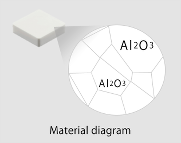 1. White Ceramic Alumina (Al2O3) is the main component of ceramic, and is called white ceramic because of its color. In fact, the same ingredients are in jems like rubies and sapphires (Al2O3) The main difference is that ruby and sapphire are single crystals (particles of one large mass), while alumina is polycrystalline (a collection of multiple particles). Alumina is hard and chemically stable. Taking advantage of its properties, it is used in high-speed finishing of cast iron. 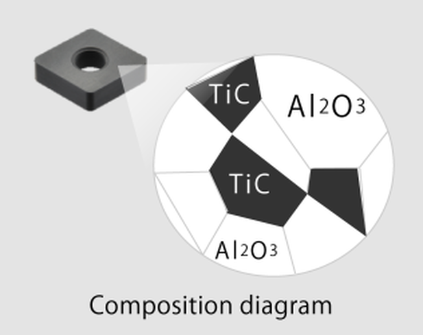 2. Black Ceramic Titanium carbide (TiC) is added to alumina, and this is called black ceramic because of its color. The addition of titanium carbide results in higher hardness, than white ceramic, and suppresses deformation of the cutting edge due to heat; even at high temperatures. Taking advantage of its properties, it is used in high-speed finishing of hardened materials up to about HRC65. 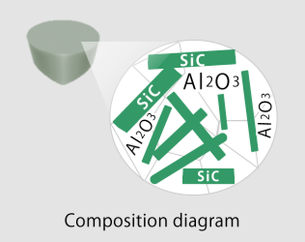 3. Whisker It is a ceramic in which silicon carbide (SiC) is added to alumina. Do you know why it’s called whisker ? Silicon carbide has a needle-like shape similar to a “animal beard”, so it is now called whisker (ceramic). By intertwining silicon carbide with each other, the progression of cracks due to impacts during cutting is suppressed, and cracks are prevented. In addition, it has a resistance against sudden temperature changes. Taking advantage of these properties, it is widely used for heat-resistant alloy processing. Silicon nitride, Si3N4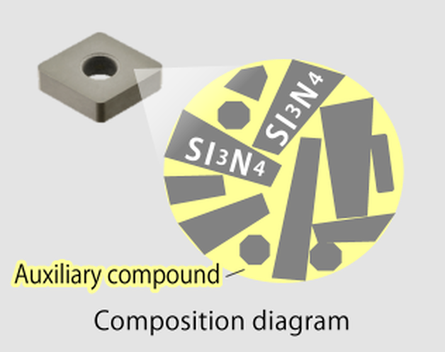 5. Silicon Nitride Silicon nitride (Si3N4) is the main component, and a special feature is that the particles are needle-like, different from the alumina compound. By intertwining needle-like particles, the progression of cracks due to impact during cutting can be greatly suppressed, preventing cracks. Taking advantage of these properties, it is used in high-speed roughing of cast iron. 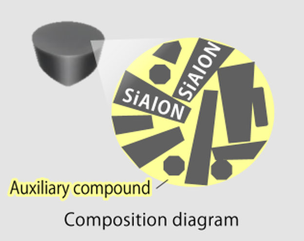 5. Sialon Silicon nitride (Si3N4), Aluminum (Al), and oxygen (O)are blended to form SiAlON, which is an initial of its component elements. Sialons, like silicon nitride, have needle-like particles. Needle-like particles intertwine to withstand impact during cutting. In addition, the effect of the added alumina component improves heat resistance over silicon nitride, and has excellent high temperature resistance characteristics. Taking advantage of these properties, it is used in high-speed processing of heat-resistant alloys. The table below shows typical machining application examples of ceramic cutting tools.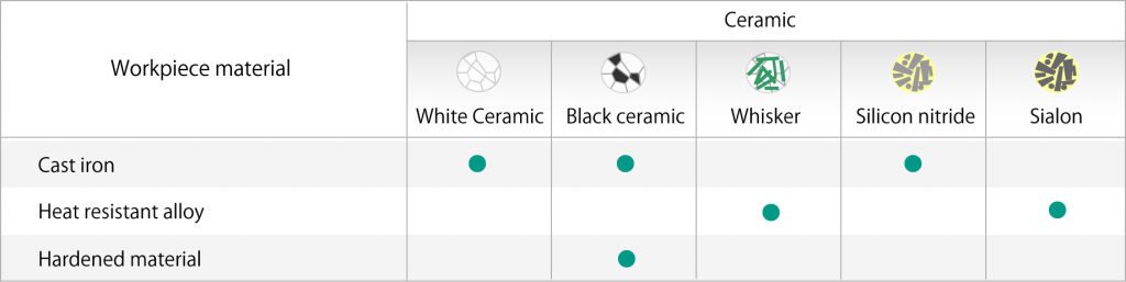 We hope this column gave you a better understanding of the types, differences, and features of ceramic materials.
Ceramic cutting tools must be used according to the material to be machined, but they can be processed up to 20 times faster than carbide tools. Increase productivity with ceramic cutting tools for your material applications. About the author: Jack Burley, Vice President of Sales and Engineering and Big Kaiser Precision Tooling Inc. Micromachining, cutting where the volume of chips produced with each tool path is very small, is not a high-speed operation in relation to chip load per tooth. Rather, it involves a high spindle speed relative to cutter diameter. The part may be physically larger, but details of the part require ultra-small profiles achieved only by micromachining. In other words, micromachining is not limited in scope to only miniature parts.  Big Kaiser considers tools with <3mm to be micro tools with unique geometric considerations. TOOLHOLDING In medical work, where tight tolerances are standard, dynamic runout; the measurement of the spindle at high speeds, performed using laser or capacitance resistance technology, and balance must be controlled to deliver and maintain viable tool life.
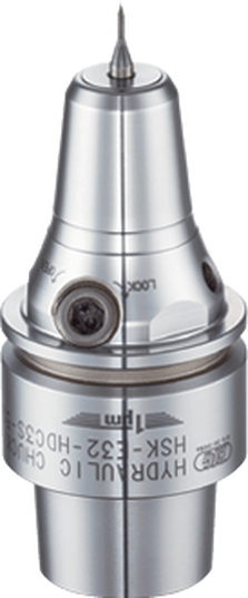
A holder with 0.00060" runout accuracy produced nearly two-thirds fewer holes, only 800. In this scenario, the shop could save hundreds of dollars a month in carbide costs – as well as labor costs due to less tool changing – by making one smart tool holder choice. Holder attributes that can boost production include symmetrical design, a perfectly concentric collapse of the collet around the cutter, and a ball-bearing raceway nut with precision-ground threads. CHALLENGES While these characteristics are good rules of thumb, things change fast in this field and, like our customers, we must adapt as trends emerge. Batch sizes are getting smaller. Bone screws, for example, were typically run on multi-axis, Swiss-type lathes where the same tools and programs ran for days at a time. Traditionally, prototyping in this arrangement was not an option because of the complexity and time involved in programming and setup. Today’s need for customized sizes demands flexibility and quick changeover to remain productive. We are investing a large portion of our research and development (R&D) in tackling this challenge. We are working on hydro-clamping tool holder systems that could make the decades-long approach of using ER collets obsolete. It would make it possible, for example, to perform a simple drill change on a gang slide in seconds. COOLANTS Another trend in medical manufacturing being driven by the U.S. Food and Drug Administration (FDA) is clean machining without the use of water-soluble coolants.
We are focusing on two features:
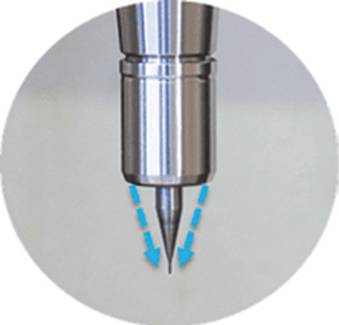
 Matching medical components to each patient demands flexibility. This hydro- clamping tool holder system for Swiss-type lathes would make the decades-long approach of using ER collets obsolete by making it possible to perform a simple drill change on a gang slide in seconds. TOOLING Tool considerations also must be taken into account to keep up with the demanding medical field. Better results often cannot be achieved by simply increasing spindle speeds or using smaller tools; a deeper understanding of cutters is necessary. We consider tools with diameters <3mm to be micro tools. These aren’t simply smaller versions of their macro counterparts. They have geometric considerations all their own. For example, the 1mm Sphinx drill can run at 80xD. But this is only possible because the cylindrical shaping extends further down the tool, closer to the tip, to facilitate pecking and maintain strength. Tool carbide should be ultra-fine grain (nano or submicron grain size) to ensure high abrasion resistance and good toughness. Coatings are valuable too, but it’s important to understand how coatings can negatively impact micro tool performance. Micro tools have extremely fine surface finishes and sharp cutting edges. Coatings can fill in valuable space – a flute on a drill, for example – needed for proper chip evacuation, which is critical in these applications. Coatings must be ultra-thin (<1µm) and smooth; our experience shows that misapplied coatings result in poor tool life due to breakage; the coating reduces cutting edge sharpness, increasing torque force on the drill. When coating is necessary, consult with the cutting tool manufacturer to provide this directly. Chips and small tooling naturally do not get along well. Compensating for low spindle speeds with tools that have more flutes support an ideal feed rate, but chip evacuation may suffer. Determining the appropriate chip load – as close to the cutting edge as possible – allows operations at the highest possible spindle speed, accelerating the cycle and improving surface finish. Optimal conditions exist when the chip load is relatively equal to the cutting edge radius. Many micro end mills are designed so the cutting edge radius has a positive rake angle to create a shearing action. A chip load less than the cutting edge radius often results in a negative rake angle where the tool rubs rather than cuts. This increases the force required and generates more heat which can result in built-up edges and poor tool life. A chip load significantly bigger than the cutting edge radius often leads to premature failure because the tool is not robust enough to withstand such forces. MACHINE TOOLS
Micromachining requires machine tools with very high sensitivity, fine resolution in the feed axis, and very precise spindles capable of high speed with low dynamic runout. For micro-drilling operations, specialized micro machines are best. Micro milling machines are suited for small tools and small workpieces. They are characterized by spindle speeds faster than 50,000rpm using small HSK tool holders such as HSK-E32, E25, or E20. With the right holder, tool runout can be controlled to less than 1µm (0.000040") at the cutting edge, ensuring sub-micron accuracy. In medical micromachining, understanding each piece of the equipment puzzle is critical. It’s also important not to make assumptions based on other tools or parts you may have worked with, especially in more standard sizes. Invest the right time and energy in gearing up for the next medical job and you’ll get more parts done right faster. |
Technical Support BlogAt Next Generation Tool we often run into many of the same technical questions from different customers. This section should answer many of your most common questions.
We set up this special blog for the most commonly asked questions and machinist data tables for your easy reference. If you've got a question that's not answered here, then just send us a quick note via email or reach one of us on our CONTACTS page here on the website. AuthorshipOur technical section is written by several different people. Sometimes, it's from our team here at Next Generation Tooling & at other times it's by one of the innovative manufacturer's we represent in California and Nevada. Archives
March 2024
Categories
All
|

 RSS Feed

About
|
© 2024 Next Generation Tooling, LLC.
All Rights Reserved Created by Rapid Production Marketing
|
