|
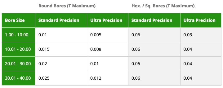
Not sure which level of precision you need to order for your workholding collet? Tecnicrafts has put together this easy to understand chart that explains the difference between "standard" precision and "ultra" precision for both round stock and hex stock. The tolerance is based upon your ore size. We hope you find this helpful! Call us with questions! 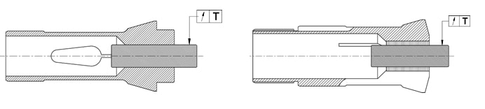 Tecnicrafts Industry is an ISO 9001:2015 Certified Company
0 Comments
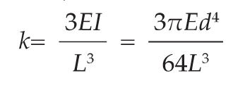
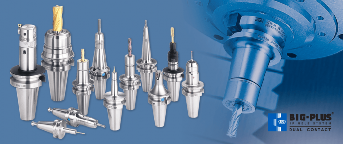 Spindles and tool holders are in a constant battle with the forces of nature, with this battle becoming more and more difficult with heavier cuts and longer projections. Chattering and deflection have always been the bane of machinists’ existence, so much so that the sight of a long and slender toolholder will immediately cause goosebumps. If you understand why a long tool holder behaves the way it does, you’ll know that there are ways to fight back against this bending. Every machinist knows that short and stubby holders are more resistant to deflection than long and slender holders. You’ve also probably heard that, if possible, you’ll want most of your cutting forces to be axial rather than radial. Not only does this fight chatter in operations like boring, but your spindle also is better equipped to handle loads in this axis. However, these options aren’t always going to be on the table, especially in unavoidable long-reach situations and many milling operations. In this constant battle with tool deflection, much time and effort has been spent designing shorter holders, stiffer tools, and clever anti-vibration geometry and materials. But oftentimes, the body diameter(s) of the holder can be overlooked as a means of increasing rigidity, especially in situations where it is all you have to work with. This is a serious shame, as you’ll soon discover. The concept of dual-contact technology has been around for years, existing in many different forms but always with the same goal of capitalizing on this untapped potential of rigidity. For those who don’t know, dual contact refers to the shank contacting the spindle taper and the spindle face simultaneously. Oftentimes, the solution involved ex post facto alterations to the spindle or tool holder, such as using ground spacers or shims to close the gap, for example. In other words, there was no standard solution, and if you wanted dual contact, you would have to be prepared to spend time and money either buying modified tool holders or modifying them yourself to adapt them to your spindle. BIG-PLUS emerged as a solution to this issue. Essentially, both the spindle and tool holder were ground to precise specifications so that they closed the gap between spindle face and flange in unison (while depending on very small elastic deformation in the spindle). What this meant is that operators were able to confidently switch BIG-PLUS tooling in and out of a BIG-PLUS spindle and achieve guaranteed dual contact. Not only that, but standard tooling could still be used in a BIG-PLUS spindle if necessary, and vice versa. Though not technically an international standard, it’s been adopted by many machine tool builders because of the clear performance improvements and simplicity. In fact, BIG-PLUS spindles come standard on more machines than you would think. We often come across operators that have machines with BIG-PLUS spindles and don’t even realize it. 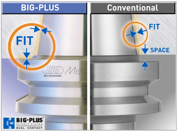 How exactly does dual contact help with tool rigidity? The torque (or moment) exerted by the cutting forces is maximized at the point where the holder and spindle meet, the base of the tool holder. With standard CAT40 tool holders, this would be the gage line diameter. When the holder contacts the spindle face via BIG-PLUS, the effective diameter would be the larger diameter of the v-flange, since this is the new anchoring point of the holder and spindle. So, you are beefing up the diameter at the point where the reactionary force is greatest. It’s not too much of a leap to conclude that a larger effective diameter will give you more rigidity. That being said, you may still be asking yourself: does such a seemingly small increase in diameter really make a difference? To understand the effect of BIG-PLUS, you must understand the physics behind it. Imagine a simple scenario in which a tool holder is represented by a cylindrical bar that is fixed at one end and free-floating at the other. In other words, a cantilever beam. If you think about it, this is essentially what a tool holder becomes once it’s secure in the spindle. Now, let’s introduce a radial force F that acts downward at the suspended end of the bar, which represents a cutting force you would encounter when milling or boring, for example. The bar, as you might expect, will want to bend downward. It’s similar to how a diving board bends when someone stands at the end, though less exaggerated. 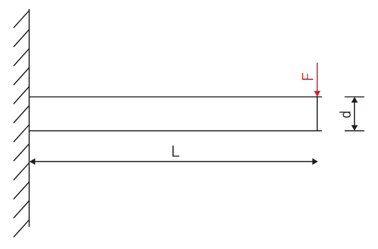 It’s possible to predict the amount of deflection (or inversely, bending stiffness) at the end of this hypothetical bar if you know its length, diameter and material. The expression below represents the stiffness k at the end of the bar where d=diameter, L=Length and E=Modulus of Elasticity
I won’t ask you to do any math here, I just want you to look at the equation. We can see that increasing d will increase the value of k, while increasing L will decrease the value of k, since it’s in the denominator of the equation. This certainly makes sense if you think about it: a short and squat bar (large d, small L) will be more rigid than a long and slender bar (small d, large L). Something interesting to note is that d is raised to the 4th power, while L is only raised to the 3rd power. Diameter affects rigidity an entire order of magnitude more than the length does. This is where the power of BIG-PLUS comes from and is why a small increase in diameter can have such a powerful effect on performance.  For a CAT40 tool holder, the gage line diameter is Ø44.45 mm and the flange diameter is Ø63.5 mm. Let’s imagine two bars of identical length and material, so L and E remain unchanged. One bar has a diameter of Ø44.45 mm (standard CAT40) and the other has Ø63.5 mm (BIG-PLUS CAT40). If you were to plug these values into the above equation for comparison, you would find that the BIG-PLUS holder results in a k value that is around 4 times greater than the standard bar. Based on this comparison, you could say that a BIG-PLUS holder is 4 times as rigid as an identical standard CAT40 holder, because it is 4 times as resistant to deflection. Think of the tool life and surface finish improvements you would see with a tool that is 4 times more rigid, not to mention the reduction in fretting and potential for reduced cycle time. You would get similar results if you were to make the same comparison for CAT50, BT40, BT30, etc.  If you’re still not convinced, we can also compare the rigidity in this way: Let’s say there is a Ø63.5 mm BIG-PLUS CAT40 bar of some arbitrary length. One of our more common gage lengths is 105 mm, or just over 4 inches, so let’s use it as an example. You’re probably wondering, at what length would a comparable standard CAT40 holder have an equal stiffness? If we take our stiffness expression and set it equal to itself (one side representing BIG-PLUS, the other non BIG-PLUS), we can plug in this BIG-PLUS holder length and our known diameters to find our unknown non-BIG PLUS length: 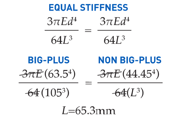 What does this mean? A BIG-PLUS holder of around 4 inches or 105 mm in length will have equal rigidity to a standard CAT40 holder of around 2.5 inches or 65 mm in length. Any experienced machinist will know quite well the difference in rigidity between a 4-inch long holder and a 2.5-inch long holder.
If this is true, we can say that implementing BIG-PLUS is equivalent to a 40% reduction in length in terms of rigidity. Theoretically, a BIG-PLUS tool holder will behave like a standard tool holder that is nearly half of its length! Obviously, we’ve used simple and idealized cases here to represent the complicated and dynamic world of metal cutting. Tool holders, of course, don’t have uniform body diameters or materials and the cutting forces usually aren’t acting in one direction in a constant and predictable way. If our holder necks up and down to different body diameters along its length, which is realistically what happens, each of these sections would be its own microcosm of “beam” that would influence the overall behavior (at that point, finite element analysis on a computer becomes the only practical way to predict behavior). So, will the advantage of BIG-PLUS really be as dramatic as our hand-calculated classical beam theory suggests? Probably not, but it depends on the tool holder/tool. Most cases will follow our simple model quite closely in practice; others not so much. If nothing else, we’ve demonstrated how dramatically the flange contact of BIG-PLUS can influence rigidity, at least in a purely mathematical sense. As if you needed any more reasons to be on the BIG-PLUS bandwagon besides increased rigidity, you will also eliminate Z-axis movement at high speeds, improve ATC repeatability and decrease fretting. This means that you will take heavier cuts, scrap less parts, and increase tool and spindle life. BIG-PLUS isn’t a new idea by any means, but with a proven track record of tackling tough jobs, it’s hard to imagine working in a modern machine shop and not taking advantage of what it has to offer. If you’re still not convinced, we can also compare the rigidity in this way: Let’s say there is a Ø63.5 mm BIG-PLUS CAT40 bar of some arbitrary length. One of our more common gage lengths is 105 mm, or just over 4 inches, so let’s use it as an example. You’re probably wondering, at what length would a comparable standard CAT40 holder have an equal stiffness? If we take our stiffness expression and set it equal to itself (one side representing BIG-PLUS, the other non BIG-PLUS), we can plug in this BIG-PLUS holder length and our known diameters to find our unknown non-BIG PLUS length: We are very excited to announce that we are now able to offer on-site technical training to YOUR machinists at YOUR location! This is offered at no charge to customers who use any of the manufacturer's whom we represent in California and Nevada. However, just because you don't purchase things from us, don't feel left out! We also offer on-site topic specter training on any of the following topics for $150/hour. Each presentation lasts about 2 hours. The presentations last approximately 45-60 minutes with the remaining time for Q&A and discussion about unique applications in your facility.  Training Classes Available: Machining 101
Advanced Part Manufacturing:
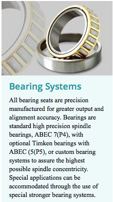
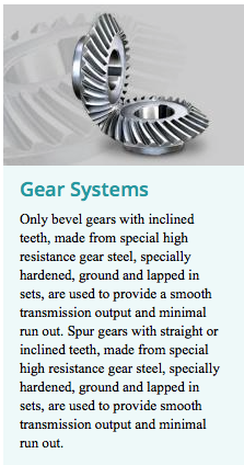
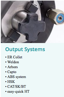
Matt Saccomanno, the inventor of the Microconic Workholding system discussed how it works at IMTS 2016. Masa Tool has developed the Microconic™ system specifically for holding workpieces from Ø0.15mm to 10mm (Ø0.006" to 0.390") in any machine that has a collet-type chuck. The system consists of two major components: The Microconic™ cartridge, which fits into your CNC machine spindle replacing the standard 5C, TF20 or TF25 collets, and the Microconic™ collet, which fits in the Microconic™ cartridge. The Microconic™ system has unsurpassed concentricity: Our manufacturing tolerance is 3µm (.0001") and we guarantee our cartridges to be within 5µm (0.0002") in production use in your machine. The Microconic™ system works with either draw-type or push-type standard collet systems that are in any machine. The Over-grip collet capabilities of Masa Microconic™ System, introduces a whole new world of time saving opportunities awaiting. Our Overgrip Collets open up to 4mm (0.157") diameter larger than the clamping diameter. by, Preben Hansen is President of Heimatec Inc. Live tooling is driven by the CNC control and the turret of various spindle and powered sub-spindle configurations on CNC lathes to perform various operations while the workpiece remains in orientation to the main spindle. These devices, whether BMT or VDI, are also called driven tools, as opposed to the static tools used during turning operations and are usually customized for the particular machine tool builder’s turret assembly. A common error is often made by accepting the standard tooling packages provided by the builder. This is not a criticism of the standard packages from builders, but this article is meant to give you a set of parameters to consider when evaluating the tooling and toolholding devices to use in your shop or production department. Do as much evaluation of your process, when determining the proper tooling to be used, as you did when you evaluated the various machines available for purchase. Identical Job, Different Tooling RequirementsTool life is the product of cutting intensity, materials processed, machine stability and, of course, piece parts produced. Two seemingly identical job shops can have vastly different tooling needs because one is automotive and one is medical, or one specializes in the one-offs and low-volume work, while the other has a greater occurrence of longer run jobs. The totality of your operation determines the best tooling for the machines being purchased. Bearings & Gears Bearing construction and the resulting spindle concentricity drive the life of any tool and you might find a 10-15 per cent greater investment in a better design can yield longer lasting cutters and consistently superior finish on your products.
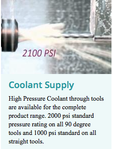
Coolant, RPM & 2nd Op Considerations Also look for an internal vs. external collet nut, so the tool seats more deeply in the tool, as superior rigidity will result. Likewise, coolant high pressure might be desirable. Look for 2000 psi in 90o and 1000 psi minimum in straight tools.
Standard live tooling is best suited to production work, where the finish, tolerances and cutter life are critical, while quick-change systems may be better suited to the shop producing families of products and other instances where the tool presetting offline is a key factor in keeping the shop at maximum productivity. Long-Term Flexibility
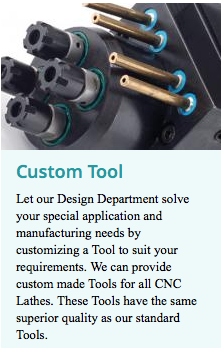
Dedicated tools for large families of product may be desirable, but consider a changeable adapter system and talk to your supplier before making that determination.
Adjustable angle head systems can be costly, but worthwhile, owing to the stability and rigidity of their construction, when producing families of parts with only slight differences in the dimensions.
As the CNC manufacturing industry continues to grow we're meeting more and more new people coming into our industry. Although many experienced machinists have lots of knowledge, we're finding that the new people are asking questions about some things that may be common knowledge to the old hands. One of the questions relates to "Why the heck is the cone on the toolholder the angle that it is?" We're here to help answer that.... By now, many have undoubtedly heard that most steep taper (CAT, BT) Toolholders hold an AT3 taper tolerance or better. So what exactly is AT3? Steep Taper, Fast Tapers & Locking TapersBefore we get into the tolerance and specs it's important to understand that there are basically two classes of tapers:
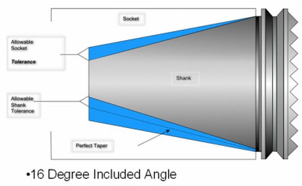 Most of the taper standards originated in the early days of the aircraft industry with rotors and propellers. There's quite a bit of thought that went into why the two types of tapers exists: It has a lot to do with "Van der Waals Forces" if you want to know about it in more detail. What's important to know is that CNC spindles are made with Steep Tapers. Why? Well, just as the two names state the first is "locking" taper and the second is "free-releasing" Since Toolholders have to be automatically changed in the CNC machine you want them to be as close to a locking taper as possible (8°/side) without, well, 'locking' in place (7°/side)! This is also the reason the ER/DR style collets also are made to an 8°/side angle as well by-the-way. What is an AT3 Taper Tolerance?That brings us to the "AT" standard for steep tapers. "AT" is an ANSI/ASME (ASME B5.50-1994) and ISO Standard (ISO 1947 ) that runs from AT1 to AT11. Since the AT tolerance is essentially logarithmic, the lower the number the tighter the tolerance (and harder it is to 'hit' in manufacturing). In other words the difference between AT 3 and AT4 is NOT the same increase in tolerance as between AT3 and AT2. AT3 is harder to attain than AT4 and AT 2 is substantially harder to reach than the jump from AT 4 to AT3. Again, the lower the number, the tighter the 'self releasing' tolerance. Most CNC Machines steep taper spindles are made to an AT2 Specification. In order to stay competitive most all toolholder manufacturers are holding an AT3 tolerance (or better). Because there are much fewer spindles made than rotary toolholders this makes manufacturing sense. The key words here to pay attention to is "or better" Just like when you make parts in your shop to a tolerance, that doesn't mean that every part is exactly the same. The parts are within a tolerance band. That's what the "AT" defines! So when a toolholder manufacturer says "AT3 or better" that can mean that some of the holders are actually holding an AT2 tolerance... and this is sometimes the cause of the tolholders 'sticking' in the spindle:Not because they are out of tolerance, but because they are actually holding a closer tolerance! (...nearer a locking taper) By-the-way, most all steep taper toolholders are made from some derivative of 8620 steel and then case hardened. Steep Taper Rotary Toolholder are Taper DrivenSo although most people think that the drive dogs on the spindle are doing the 'driving' of the rotation of the toolholder, it's actually the taper connection that is driving the rotation of the tool. If that wasn't the case, then you would see the drive dog notches in the toolholder start to show signs of wear when the spindle impacted them all the time. Afterall, the 8620 is only case hardened.
There are a couple of last things to make note of and think about:
Some further reading: 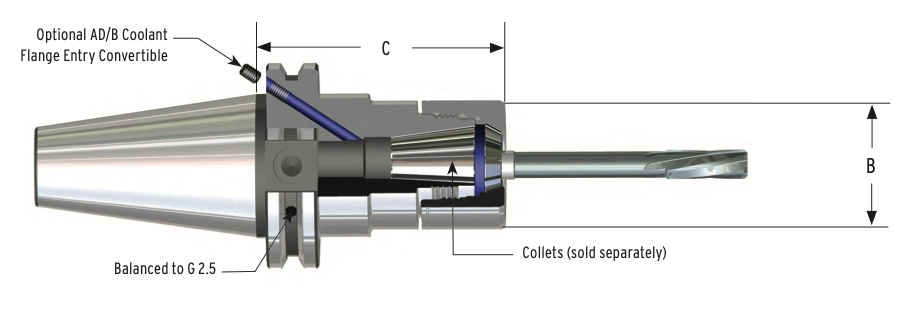 We often get asked to spec out tooling packages for new CNC mills and one of the questions we encounter most, or should, is how do you select the right toolholder collet size for your companies applications? The real choice is in the size of the collet chuck itself. So several considerations should be reviewed... What size are your tools?Your first consideration should be the size of end mills or drills you will be using most often. If you are doing smaller work you would require smaller diameter range collets. Generally you may prefer the ER16 and ER32 sizes. If you are doing very small work then perhaps an ER11 set would be the best choice. If the bulk of your tool requirements are in the mid range you can also use the ER20. The following is a list of tool diameters that can be used with each size collet chuck. Essentially, the most popular, and again, readily available from a number of sources, are the ER 16, ER20, and ER32... in no particular order.
If you need more detailed list of dimensions can be found at these links: 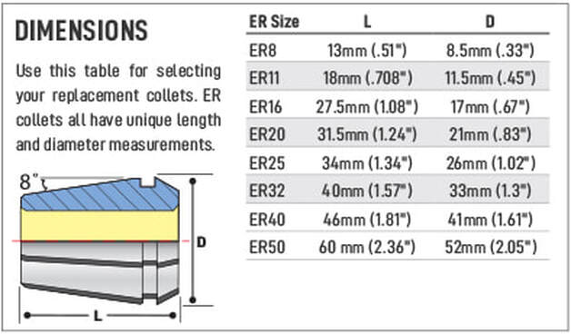 How far do you need to reach?A second consideration is the actual reach of the tool. Not projection reach, also know as “gage length” "l1" but projection diameter “D”. Obviously, stubbier is better for projection reach "L1". But, you also need to review the families of parts that you intend to run on the machine. If you intend to use the holder to "reach" into a tight fit then the OD of the projection "D" of the toolholder needs to be considered. Many shops don't always consider this and end up using much longer carbide shanked end mills to get into deep pockets when getting a smaller diameter ER collet and collet chuck would be much less expensive over the life of the job. 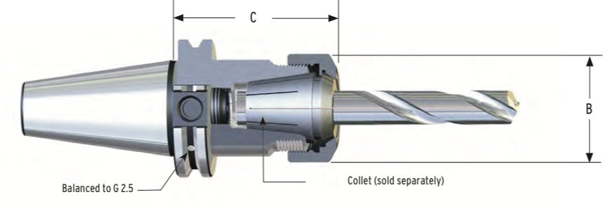 Here is a list of the OD projection diameters:
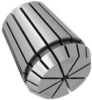
Sometimes there is just no getting around having a custom tool made. Get in contact with us if you just can't seem to reach into the part with your toolholder. 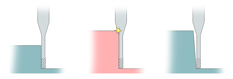 by Bernard Martin ER, IT’S IN THE DETAILS The ER collet system has several advantages when using today's CNC computerized milling machines. The most significant advantage is flexibility to hold any type of round shank tool. An ER collet can be used in drilling, reaming, and tapping as well as milling applications just by exchanging the collet. Its accuracy also provides greater tool life than older style collet systems like TG or DA. Another advantage is the flexibility of the collet for clamping a wide range of tool shanks with a small number of collets. ER 16 through ER 40 provide a collapse range of ~.039" flexibility for clamping cutting tools. This is a benefit for you because you will not have to carry as many collets in inventory for the different jobs you need to do each day. The ER collet also provides more holding power by using two principles. 
In addition to mechanical differences, the ER collet is also user friendly. It is a self-extracting collet, which eliminates the need for collet squeezers to extract the collet by any other means than screwing the nut off. This enables the operator to spend time running the machine, not extracting collets. These basic principles allow the ER collet system to be the most widely accepted collet system in the world for holding round shank cutting tools. 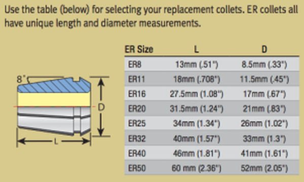
ER style collet chucks should be used for the bulk of your needs. They are the most dependable, with the least runout, both in and out of the cut, are readily available (so the prices continue to drop) and will give you the best tool life out of the lot of them. Advantages of the ER Collet System |
Technical Support BlogAt Next Generation Tool we often run into many of the same technical questions from different customers. This section should answer many of your most common questions.
We set up this special blog for the most commonly asked questions and machinist data tables for your easy reference. If you've got a question that's not answered here, then just send us a quick note via email or reach one of us on our CONTACTS page here on the website. AuthorshipOur technical section is written by several different people. Sometimes, it's from our team here at Next Generation Tooling & at other times it's by one of the innovative manufacturer's we represent in California and Nevada. Archives
March 2024
Categories
All
|
 RSS Feed

About
|
© 2024 Next Generation Tooling, LLC.
All Rights Reserved Created by Rapid Production Marketing
|
